Lincoln Aviator 2020-2025 Service Manual / Body and Paint / Body and Paint / Roof Opening Panel / Description and Operation - Roof Opening Panel - Overview

Lincoln Aviator: Roof Opening Panel / Description and Operation - Roof Opening Panel - Overview

Roof Opening Panel

The roof opening panel consists of the following:

  • Air deflector
  • Sliding glass panel
  • Sliding glass panel motor
  • Shield assembly
  • Shield motor
  • Roof opening panel fixed glass
  • Roof opening panel frame assembly
  • Roof opening panel drain hoses
  • Roof opening panel control switch
  • Roof opening panel seal

The roof opening panel motor must be initialized when repairs are carried out on the roof opening panel system, including: any time the roof opening panel motor has been removed, the roof opening panel glass (sliding or fixed glass) has been removed or adjusted, or if the roof opening panel frame has been removed.
For additional information, refer to: Power Roof Opening Panel Initialization (501-17 Roof Opening Panel, General Procedures).

The accessory delay relay, located in the BCM, that provides voltage for the operation of the power windows and the roof opening panel.
For additional information, refer to: Glass, Frames and Mechanisms - System Operation and Component Description (501-11 Glass, Frames and Mechanisms, Description and Operation).

The roof opening panel is an electronically operated glass panel that can be opened, closed or tilted (vent position) by the roof opening panel control switch, the shield switch, and the vent switch. Actuating the switches supplies a signal to the roof opening panel glass and shield motor/module. The front sliding glass panel and the shield use two integrated motors/modules that are serviced as assemblies. The roof opening panel and shield has one-touch open and one-touch close features that are activated when the switch is pressed and immediately released (less than 0.5 seconds) on the open or close side of the switch. For manual control holding the switch depressed for more than 0.5 seconds will cancel one-touch operation and the sliding glass panel or shield will stop when the switch is released.

Additionally there is a roof opening panel fixed glass panel behind the sliding glass panel. The roof opening panel fixed glass is attached with 4 screws and can be aligned.

    Specifications

      Specifications Item Specification Rear fixed glass panel to roof flushness, side (at front of glass) 0 ± 0...

    Description and Operation - Roof Opening Panel - System Operation and Component Description

    System Operation Roof Opening Panel Operating System The accessory delay relay in the BCM supplies voltage through fuse F2 (10A) to the roof opening panel sliding glass motor and roof opening panel shield motor allowing the motors to respond to roof opening panel control switch commands...

    Other information:

    Lincoln Aviator 2020-2025 Service Manual: Diagnosis and Testing - Headlamps


    Diagnostic Trouble Code (DTC) Chart Diagnostics in this manual assume a certain skill level and knowledge of Ford-specific diagnostic practices. REFER to: Diagnostic Methods (100-00 General Information, Description and Operation).   Diagnostic Trouble Code Chart Module   DTC Description Action   BCM B14E0:11 Exterior Lamps Power Supply "C": Circuit Short to Ground   GO to Pinpoint Test A   BCM B14E0:15 Exterior Lamps Power Supply "C": Circuit Short to Battery or Open   GO to Pinpoint Test A   BCM B14E1:11 Exterior Lamps Power Supply "D": Circuit Short to Ground   GO to Pinpoint Test A   BCM B14E1:15 Exterior Lamps Power Supply "D": Circuit Short to Battery or Open   GO to Pinpoint Test A   BCM B14E2:11 Exterior Lamps Power Supply "E": Circuit Short to Ground   GO to Pinpoint Test B   BCM B14E2:15 Exterior Lamps Power Supply "E": Circuit Short to Battery or Open   GO to Pinpoint Test B   BCM B14E3:11 Exterior Lamps Power Supply "F": Circuit Short to Ground   GO to Pinpoint Test B   BCM B14E3:15 Exterior Lamps Power Supply "F": Circuit Short to Battery or Open   GO to Pinpoint Test B   BCM B14E5:01 Left Front Enhanced Exterior Lighting System: General Electrical Failure   GO to Pinpoint Test S   BCM B14E5:08 Left Front Enhanced Exterior Lighting System: Bus Signal / Message Failure   GO to Pinpoint Test S   BCM B14E5:49 Left Front Enhanced Exterior Lighting System: Internal Electronic Failure   GO to Pinpoint Test S   BCM B14E5:55 Left Front Enhanced Exterior Lighting System: Not Configured   GO to Pinpoint Test S   BCM B14E7:01 Right Front Enhanced Exterior Lighting System: General Electrical Failure   GO to Pinpoint Test S   BCM B14E7:08 Right Front Enhanced Exterior Lighting System: Bus Signal / Message Failure   GO to Pinpoint Test S   BCM B14E7:49 Right Front Enhanced Exterior Lighting System: Internal Electronic Failure   GO to Pinpoint Test S   BCM B14E7:55 Right Front Enhanced Exterior Lighting System: Not Configured   GO to Pinpoint Test S   BCM B1533:02 Headlamp Switch Module: General Signal Failure   GO to Pinpoint Test A   BCM B1533:08 Headlamp Switch Module: Bus Signal / Message   GO to Pinpoint Test A   BCM B1533:49 Headlamp Switch Module: Internal Electronic Failure   GO to Pinpoint Test A   BCM B1533:56 Headlamp Switch Module: Invalid / Incompatible Configuration   GO to Pinpoint Test A   BCM B1D00:11 Left Low Beam: Circuit Short To Ground   GO to Pinpoint Test A   BCM B1D00:15 Left Low Beam: Circuit Short To Battery Or Open   GO to Pinpoint Test A   BCM B1D01:11 Right Low Beam: Circuit Short To Ground   GO to Pinpoint Test A   BCM B1D01:15 Right Low Beam: Circuit Short To Battery Or Open   GO to Pinpoint Test A   BCM B1D02:11 Left High Beam Circuit: Circuit Short To Ground   GO to Pinpoint Test B   BCM B1D02:15 Left High Beam Circuit: Circuit Short To Battery Or Open   GO to Pinpoint Test B   BCM B1D03:11 Right High Beam Circuit: Circuit Short To Ground   GO to Pinpoint Test B   BCM B1D03:15 Right High Beam Circuit: Circuit Short To Battery Or Open   GO to Pinpoint Test B   HCM B1041:04 Levelling Control: System Internal Failure   GO to Pinpoint Test H   HCM B1041:54 Levelling Control: Missing Calibration   GO to Pinpoint Test H   HCM B1087:83 LIN Bus "A": Value of Signal Protection Calculation Incorrect   GO to Pinpoint Test F   HCM B1087:83 LIN Bus "A": Value of Signal Protection Calculation Incorrect   GO to Pinpoint Test G   HCM B1087:86 LIN Bus "A": Signal Invalid   GO to Pinpoint Test F   HCM B1087:86 LIN Bus "A": Signal Invalid   GO to Pinpoint Test G   HCM B1088:83 LIN Bus "B": Value of Signal Protection Calculation Incorrect   GO to Pinpoint Test F   HCM B1088:83 LIN Bus "B": Value of Signal Protection Calculation Incorrect   GO to Pinpoint Test G   HCM B1088:86 LIN Bus "B": Signal Invalid   GO to Pinpoint Test F   HCM B1088:86 LIN Bus "B": Signal Invalid   GO to Pinpoint Test G   HCM B1437:01 Left Levelling Actuator: General Electrical Failure   GO to Pinpoint Test I   HCM B1437:87 Left Levelling Actuator: Missing Message   GO to Pinpoint Test F   HCM B1437:87 Left Levelling Actuator: Missing Message   GO to Pinpoint Test G   HCM B1439:01 Right Levelling Actuator: General Electrical Failure   GO to Pinpoint Test I   HCM B1439:87 Right Levelling Actuator: Missing Message   GO to Pinpoint Test F   HCM B1439:87 Right Levelling Actuator: Missing Message   GO to Pinpoint Test G   HCM B14D9:01 Left Headlamp Light Distribution Actuator: General Electrical Failure   GO to Pinpoint Test I   HCM B14D9:64 Left Headlamp Light Distribution Actuator: Signal Plausibility Failure   GO to Pinpoint Test I   HCM B14D9:87 Left Headlamp Light Distribution Actuator: Missing Message   GO to Pinpoint Test F   HCM B14D9:87 Left Headlamp Light Distribution Actuator: Missing Message   GO to Pinpoint Test G   HCM B14DA:01 Right Headlamp Light Distribution Actuator: General Electrical Failure   GO to Pinpoint Test I   HCM B14DA:64 Right Headlamp Light Distribution Actuator: Signal Plausibility Failure   GO to Pinpoint Test I   HCM B14DA:87 Right Headlamp Light Distribution Actuator: Missing Message   GO to Pinpoint Test F   HCM B14DA:87 Right Headlamp Light Distribution Actuator: Missing Message   GO to Pinpoint Test G   HCM B14DB:01 Left Headlamp Driver Control System: General Electrical Failure   GO to Pinpoint Test I   HCM B14DB:54 Left Headlamp Driver Control System: Missing Calibration   GO to Pinpoint Test I   HCM B14DB:55 Left Headlamp Driver Control System: Not Configured   GO to Pinpoint Test I   HCM B14DB:87 Left Headlamp Driver Control System: Missing Message   GO to Pinpoint Test F   HCM B14DB:87 Left Headlamp Driver Control System: Missing Message   GO to Pinpoint Test G   HCM B14DC:01 Right Headlamp Driver Control System: General Electrical Failure   GO to Pinpoint Test I   HCM B14DC:54 Right Headlamp Driver Control System: Missing Calibration   GO to Pinpoint Test I   HCM B14DC:55 Right Headlamp Driver Control System: Not Configured   GO to Pinpoint Test I   HCM B14DC:87 Right Headlamp Driver Control System: Missing Message   GO to Pinpoint Test F   HCM B14DC:87 Right Headlamp Driver Control System: Missing Message   GO to Pinpoint Test G   HCM B1559:96 Left Headlamp: Component Internal Failure   GO to Pinpoint Test I   HCM B155A:96 Right Headlamp: Component Internal Failure   GO to Pinpoint Test I   HCM B15A6:01 Right Matrix Controller Actuator: General Electrical Failure   GO to Pinpoint Test I   HCM B15A6:87 Right Matrix Controller Actuator: Missing Message   GO to Pinpoint Test F   HCM B15A6:87 Right Matrix Controller Actuator: Missing Message   GO to Pinpoint Test G   HCM B15A7:01 Left Matrix Controller Actuator: General Electrical Failure   GO to Pinpoint Test I   HCM B15A7:87 Left Matrix Controller Actuator: Missing Message   GO to Pinpoint Test F   HCM B15A7:87 Left Matrix Controller Actuator: Missing Message   GO to Pinpoint Test G   HCM B1A59:1C Sensor 5 Volt Supply: Circuit Voltage Out of Range   GO to Pinpoint Test H   HCM B1D64:01 Left Headlamp Swiveling Motor: General Electrical Failure   GO to Pinpoint Test I   HCM B1D64:87 Left Headlamp Swiveling Motor: Missing Message   GO to Pinpoint Test F   HCM B1D64:87 Left Headlamp Swiveling Motor: Missing Message   GO to Pinpoint Test G   HCM B1D65:01 Right Headlamp Swiveling Motor: General Electrical Failure   GO to Pinpoint Test I   HCM B1D65:87 Right Headlamp Swiveling Motor: Missing Message   GO to Pinpoint Test F   HCM B1D65:87 Right Headlamp Swiveling Motor: Missing Message   GO to Pinpoint Test G   HCM B1D68:64 Left Headlamp Swiveling Feedback Sensor: Signal Plausibility Failure   GO to Pinpoint Test I   HCM B1D69:64 Right Headlamp Swiveling Feedback Sensor: Signal Plausibility Failure   GO to Pinpoint Test I   HCM C1A03:12 Left Front Height Sensor: Circuit Short To Battery   GO to Pinpoint Test H   HCM C1A03:14 Left Front Height Sensor: Circuit Short To Ground or Open   GO to Pinpoint Test H   HCM C1A03:29 Left Front Height Sensor: Signal Invalid   GO to Pinpoint Test H   HCM C1A03:64 Left Front Height Sensor: Signal Plausibility Failure   GO to Pinpoint Test H   HCM C1A05:12 Left Rear Height Sensor: Circuit Short To Battery   GO to Pinpoint Test H   HCM C1A05:14 Left Rear Height Sensor: Circuit Short To Ground or Open   GO to Pinpoint Test H   HCM C1A05:29 Left Rear Height Sensor: Signal Invalid   GO to Pinpoint Test H   HCM C1A05:64 Left Rear Height Sensor: Signal Plausibility Failure   GO to Pinpoint Test H   HCM U0121:00 Lost Communication With Anti-Lock Brake System (ABS) Control Module: No Sub Type Information   GO to Pinpoint Test J   HCM U0146:00 Lost Communication With Serial Data Gateway "A": No Sub Type Information   GO to Pinpoint Test K   HCM U0151:00 Lost Communication With Restraints Control Module: No Sub Type Information   GO to Pinpoint Test M   HCM U0212:00 Lost Communication With Steering Column Control Module: No Sub Type Information   GO to Pinpoint Test L   HCM U023A:00 Lost Communication With Image Processing Module A: No Sub Type Information   GO to Pinpoint Test N   HCM U0415:00 Invalid Data Received From Anti-Lock Brake System (ABS) Control Module: No Sub Type Information   GO to Pinpoint Test P   HCM U0429:00 Invalid Data received from Steering Column Control Module: No Sub Type Information   GO to Pinpoint Test P   HCM U0447:00 Invalid Data Received From Serial Data Gateway "A": No Sub Type Information   GO to Pinpoint Test P   HCM U0452:00 Invalid Data Received From Restraints Control Module: No Sub Type Information   GO to Pinpoint Test P   HCM U053B:00 Invalid Data Received From Image Processing Module A: No Sub Type Information   GO to Pinpoint Test P   HCM U2024:51 Control Module Cal-Config Data: Not Programmed   GO to Pinpoint Test O   HCM U2024:57 Control Module Cal-Config Data: Invalid / Incompatible Software Component   GO to Pinpoint Test O   HCM U2100:00 Initial Configuration Not Complete: No Sub Type Information   GO to Pinpoint Test O   HCM U2101:00 Control Module Configuration Incompatible: No Sub Type Information   GO to Pinpoint Test O   HCM U2101:56 Control Module Configuration Incompatible: Invalid / Incompatible Configuration   GO to Pinpoint Test O   HCM U2101:86 Control Module Configuration Incompatible: Signal Invalid   GO to Pinpoint Test O   HCM U2200:45 Control Module Configuration Memory Corrupt: Program Memory Failure   GO to Pinpoint Test O   HCM U3000:45 Control Module: Program Memory Failure   GO to Pinpoint Test O   HCM U3000:46 Control Module: Calibration / Parameter Memory Failure   GO to Pinpoint Test O   HCM U3003:16 Battery Voltage: Circuit Voltage Below Threshold   GO to Pinpoint Test Q   HCM U3003:17 Battery Voltage: Circuit Voltage Above Threshold   GO to Pinpoint Test R   SCCM B124C:96 Turn Indicator Stalk Switch Pack: Component Internal Failure   GO to Pinpoint Test E   SCCM B124C:9E Turn Indicator Stalk Switch Pack: Stuck On   GO to Pinpoint Test E Symptom Chart Symptom Chart: Headlamps Diagnostics in this manual assume a certain skill level and knowledge of Ford-specific diagnostic practices...

    Lincoln Aviator 2020-2025 Owners Manual: General Information


    WARNING: This battery pack should only be serviced by an authorized electric vehicle technician. Improper handling can result in personal injury or death. WARNING: Apply the parking brake, shift into park (P), switch the ignition off and remove the key before you open the hood or have any service or repair work completed...

    Categories

    Activating Intelligent Access

    The intelligent access key must be within 3 ft (1 m) of the door or luggage compartment you intend to lock or unlock.

    At a Door

    Electronic door handles are on each door. Gently depress the switch inside the exterior door handle to unlock and open the door. An unlock symbol illuminates on the door window trim indicating your vehicle is unlocked.
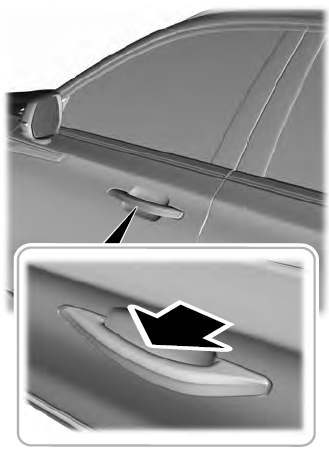
    Lincoln Aviator. Activating Intelligent Access

    read more

     
    Copyright © 2025 www.liaviator2.com