Lincoln Aviator: Second Row Climate Control / Description and Operation - Second Row Climate Control - Overview
Overview
The second row climate control system has components located in the center lower section of the climate control housing and floor console. The temperature and controls breakdown for the HVAC system is as follows, the first row driver, first row passenger, second row seating temperature and third row seating temperature.
The second row climate control system is standard equipment. The second row climate control system operation is determined by the settings on the FCIMB control panel selection, FDIM or center console controls to warm or cool the second row of the vehicle.
When equipped with a rear non touch screen RHVAC control module in the center console, the second row and third row climate controls are one zone. The climate control settings control both rows as one climate zone.
When equipped with a rear touch screen RACM climate control in the center console, the second row and third row climate controls are separate zones and are controlled independently from each other. Through a setting in the climate control system the second row climate system can be linked with the rear climate control (third row) system to have simultaneous control for both rows.
The second row climate control system air can be cooled below interior air temperature only when A/C compressor operation has been requested by the settings of the FCIMB control panel or FDIM.
 Description and Operation - Second Row Climate Control - System Operation and Component Description
System Operation
System Diagram
Item
Description
1
IPC
2
GWM
3
HVAC
4
Second row air distribution door actuator
5
Second row temperature door actuator
6
Blower motor relay
7
Second row blower motor control module
8
Second row blower motor
9
FCIMB
10
RHVAC (Rear Non touch screen)
11
Second row air discharge temperature sensor
12
Second row air flow shut off door actuator
13
RACM (Rear Touch screen)
14
APIM ( FDIM Touch Screen)
15
Rear temperature sensor - Second Row
16
Rear temperature sensor - Third Row
Network Message Charts
Module Network Input Messages - APIM
Broadcast Message
Originating Module
Message Purpose
Climate control button status
HVAC control module
This message contains the HVAC climate control settings for the touch screen display...
Other information:
Lincoln Aviator 2020-2026 Service Manual: Removal and Installation - Rocker Panel Moulding
Removal NOTE: Removal steps in this procedure may contain installation details. NOTE: LH side shown, RH side similar. Remove the rear quarter panel moulding from the affected side. Refer to: Rear Quarter Panel Moulding (501-08 Exterior Trim and Ornamentation, Removal and Installation)...
Lincoln Aviator 2020-2026 Owners Manual: Rear Interior Lamps
..
Categories
- Manuals Home
- Lincoln Aviator Owners Manual
- Lincoln Aviator Service Manual
- Opening and Closing the Hood
- Body and Paint
- Keyless Entry
- New on site
- Most important about car
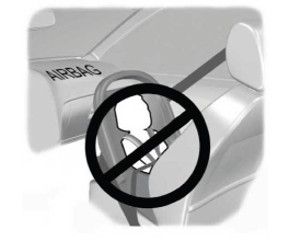
Children and Airbags
WARNING: Airbags can kill or injure a child in a child restraint. Never place a rear-facing child restraint in front of an active airbag. If you must use a forward-facing child restraint in the front seat, move the seat upon which the child restraint is installed all the way back.


