Lincoln Aviator: Rear View Camera / Using the Rear View Camera System

The rear view camera system displays what is behind your vehicle when you place the transmission in reverse (R).

Note: The reverse sensing system is not effective at speeds above 3 mph (5 km/h) and may not detect certain angular or moving objects.

The system uses three types of guides to help you see what is behind your vehicle:

  • Active guidelines (if equipped): Show the intended path of your vehicle when reversing.
  • Fixed guidelines: Show the actual path your vehicle is moving in while reversing in a straight line. This can be helpful when backing into a parking space or aligning your vehicle with another object behind you.
  • Centerline: Helps align the center of your vehicle with an object (for example, a trailer).

Note: If the transmission is in reverse (R) and the luggage compartment door is open, no rear view camera features display.

Note: When towing, the camera only sees what you are towing. This might not provide adequate coverage as it usually provides in normal operation and some objects might not be seen. In some vehicles, the guidelines may disappear when you connect the trailer tow connector.

The camera may not operate correctly under the following conditions:

  • Nighttime or dark areas if one or both reverse lamps are not operating.
  • Mud, water or debris obstructs the camera's view. Clean the lens with a soft, lint-free cloth and non-abrasive cleaner. You can also use the rear washer to clean the camera.
  • The rear of your vehicle is hit or damaged, causing the camera to become misaligned.

Camera System Settings

Depending on your vehicle options, the rear view camera system settings may be in the following:

  • Information display.
  • Touchscreen.

Note: Active guidelines are only available when the transmission is in reverse (R).
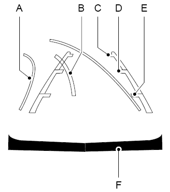
Lincoln Aviator. Using the Rear View Camera System

  1. Active guidelines (If equipped)
  2. Centerline
  3. Fixed guideline: Green zone
  4. Fixed guideline: Yellow zone
  5. Fixed guideline: Red zone
  6. Rear bumper

Active guidelines are only shown with fixed guidelines. To use active guidelines, turn the steering wheel to point the guidelines toward an intended path. If you change the steering wheel position while reversing, your vehicle might deviate from the original intended path.

The fixed and active guidelines fade in and out depending on the steering wheel position. The active guidelines do not display when the steering wheel position is straight.

Always use caution while reversing. Objects in the red zone are closest to your vehicle and objects in the green zone are farther away. Objects are getting closer to your vehicle as they move from the green zone to the yellow or red zones. Use the side view mirrors and rear view mirror to get better coverage on both sides and rear of the vehicle.

    Rear View Camera

    WARNING: The rear view camera system is a reverse aid supplement device that still requires the driver to use it in conjunction with the interior and exterior mirrors for maximum coverage...

    Object Distance Indicator (If Equipped)

    The system provides an image of your vehicle and the sensor zones. The zones highlight green, yellow and red when the parking aid sensors detect an object in the coverage area...

    Other information:

    Lincoln Aviator 2020-2025 Service Manual: Diagnosis and Testing - Parking Aid


    Diagnostic Trouble Code (DTC) Chart Diagnostics in this manual assume a certain skill level and knowledge of Ford-specific diagnostic practices. REFER to: Diagnostic Methods (100-00 General Information, Description and Operation).   Diagnostic Trouble Code Chart Module   DTC Description Action   APIM C1001:01 Vision System Camera:General Electrical Failure   GO to Pinpoint Test A   APIM C1001:01 Vision System Camera:General Electrical Failure   GO to Pinpoint Test J   APIM C1001:02 Vision System Camera:General Signal Failure   GO to Pinpoint Test A   APIM C1001:1C Vision System Camera:Circuit Voltage Out Of Range   GO to Pinpoint Test A   APIM C1001:4B Vision System Camera:Over Temperature   GO to Pinpoint Test H   APIM C1001:55 Vision System Camera:Not Configured   GO to Pinpoint Test I   APIM C1001:81 Vision System Camera:Invalid Serial Data Received   GO to Pinpoint Test A   APIM C1001:87 Vision System Camera:Missing Message   GO to Pinpoint Test A   IPMB B115E:31 Camera Module:No Signal   GO to Pinpoint Test L   IPMB B115E:49 Camera Module:Internal Electronic Failure   GO to Pinpoint Test T   IPMB B12BE:31 Left Front Camera:No Signal   GO to Pinpoint Test N   IPMB B12BE:49 Left Front Camera:Internal Electronic Failure   GO to Pinpoint Test U   IPMB B12BF:31 Right Front Camera:No Signal   GO to Pinpoint Test O   IPMB B12BF:49 Right Front Camera:Internal Electronic Failure   GO to Pinpoint Test V   IPMB B148E:31 Front Camera:No Signal   GO to Pinpoint Test M   IPMB B148E:49 Front Camera:Internal Electronic Failure   GO to Pinpoint Test W   IPMB B14A5:11 Multi-Camera View Switch:Circuit Short To Ground   GO to Pinpoint Test P   IPMB C1001:78 Vision System Camera:Alignment Or Adjustment Incorrect   GO to Pinpoint Test X   IPMB U0100:00 Lost Communication With ECM/PCM "A":No Sub Type Information   GO to Pinpoint Test Y   IPMB U0121:00 Lost Communication With Anti-Lock Brake System (ABS) Control Module:No Sub Type Information   GO to Pinpoint Test Z   IPMB U0121:87 Lost Communication With Anti-Lock Brake System (ABS) Control Module "A":Missing Message   GO to Pinpoint Test Z   IPMB U0131:00 Lost Communication With Power Steering Control Module:No Sub-Type Information   GO to Pinpoint Test AA   IPMB U0131:87 Lost Communication With Power Steering Control Module "A":Missing Message   GO to Pinpoint Test AA   IPMB U0138:00 Lost Communication with All Terrain Control Module:No Sub Type Information   GO to Pinpoint Test AB   IPMB U0140:00 Lost Communication With Body Control Module:No Sub Type Information   GO to Pinpoint Test AC   IPMB U0146:00 Lost Communication With Gateway "A":No Sub Type Information   GO to Pinpoint Test AD   IPMB U0212:00 Lost Communication With Steering Column Control Module:No Sub Type Information   GO to Pinpoint Test AJ   IPMB U0253:87 Lost Communication With Accessory Protocol Interface Module:Missing Message   GO to Pinpoint Test AK   IPMB U0293:00 Lost Communication with Hybrid/EV Powertrain Control Module:No Sub Type Information   GO to Pinpoint Test Y   IPMB U0300:57 Internal Control Module Software Incompatibility:Invalid/Incompatible Software Component   GO to Pinpoint Test AN   IPMB U0401:00 Invalid Data Received from ECM/PCM A:No Sub Type Information   GO to Pinpoint Test Y   IPMB U0415:00 Invalid Data Received from Anti-Lock Brake System (ABS) Control Module "A":No Sub Type Information   GO to Pinpoint Test Z   IPMB U0420:00 Invalid Data Received from Power Steering Control Module "A":No Sub Type Information   GO to Pinpoint Test AA   IPMB U0422:00 Invalid Data Received From Body Control Module:No Sub Type Information   GO to Pinpoint Test AC   IPMB U0423:82 Invalid Data Received from Instrument Panel Cluster Control Module:Alive/Sequence Counter Incorrect/Not Updated   GO to Pinpoint Test AE   IPMB U0424:00 Invalid Data Received From HVAC Control Module:No Sub Type Information   GO to Pinpoint Test AF   IPMB U0424:82 Invalid Data Received From HVAC Control Module:Alive/Sequence Counter Incorrect/Not Updated   GO to Pinpoint Test AF   IPMB U0428:00 Invalid Data Received From Steering Angle Sensor Module:No Sub Type Information   GO to Pinpoint Test AG   IPMB U0485:82 Invalid Data Received From Radio:Alive/Sequence Counter Incorrect/Not Updated   GO to Pinpoint Test AH   IPMB U0553:82 Invalid Data Received From Lighting Control Module-Rear "B":Alive/Sequence Counter Incorrect/Not Updated   GO to Pinpoint Test AI   IPMB U0554:00 Invalid Data Received From Accessory Protocol Interface Module:No Sub Type Information   GO to Pinpoint Test AK   IPMB U0554:82 Invalid Data Received From Accessory Protocol Interface Module:Alive/Sequence Counter Incorrect/Not Updated   GO to Pinpoint Test AK   IPMB U0594:00 Invalid Data Received From Hybrid/EV Powertrain Control Module:No Sub Type Information   GO to Pinpoint Test Y   IPMB U1000:11 Solid State Driver Protection Active -Driver Disabled:Circuit Short To Ground   GO to Pinpoint Test AL   IPMB U2024:41 Control Module Cal-Config Data:General Checksum Failure   GO to Pinpoint Test AM   IPMB U2100:00 Initial Configuration Not Complete:No Sub Type Information   GO to Pinpoint Test AM   IPMB U2101:00 Control Module Configuration Incompatible:No Sub Type Information   GO to Pinpoint Test AM   IPMB U3000:42 Control Module:General Memory Failure   GO to Pinpoint Test AN   IPMB U3000:49 Control Module:Internal Electronic Failure   GO to Pinpoint Test AN Symptom Chart(s) Rear Only Parking Aid Camera Diagnostics in this manual assume a certain skill level and knowledge of Ford-specific diagnostic practices...

    Lincoln Aviator 2020-2025 Owners Manual: Side Airbags and Driver and Passenger Knee Airbags


    Side Airbags WARNING: Do not place objects or mount equipment on or near the airbag cover, on the side of the front or rear seatbacks, or in areas that may come into contact with a deploying airbag. Failure to follow these instructions may increase the risk of personal injury in the event of a crash...

    Categories

    Child Safety Locks

    When the child safety locks are set, you cannot open the rear doors from the inside.
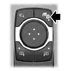
    Lincoln Aviator. Child Safety Locks

    The child safety lock control is on the driver door.

    Press the control to switch the child safety locks on. Press the control again to switch them off. A light on the child safety control illuminates when you switch them on.

    read more

     
    Copyright © 2025 www.liaviator2.com