Lincoln Aviator: Brakes / Electric Parking Brake
WARNING: Always fully apply the parking brake and make sure you shift into park (P). Failure to follow this instruction could result in personal injury or death.
WARNING: If you drive extended distances with the parking brake applied, you could cause damage to the brake system.
WARNING: The electric parking brake does not operate if the vehicle battery is running out of charge.
Your vehicle has an electric parking brake. You operate it with a switch instead of a lever. The switch is on the center console or to the left-hand side of the steering wheel, on the lower part of the instrument panel.
Note: The electric parking brake makes noises during operation. This is normal.
Applying the Electric Parking Brake
 Pull the switch upward.
 The red warning lamp flashes
during operation and illuminates
when the parking brake is applied.

Note: It remains illuminated for a short period of time after you switch the ignition off.
If it continues to flash or does not illuminate, the system has malfunctioned. Have your vehicle checked as soon as possible.
Note: You can apply the electric parking brake when the ignition is off.
Note: The electric parking brake could automatically apply when you shift into park (P).
Applying the Electric Parking Brake in an Emergency
Note: Do not apply the electric parking brake when your vehicle is moving, except in an emergency. If you repeatedly use the electric parking brake to slow or stop your vehicle, you could cause damage to the brake system.
You can use the electric parking brake to slow or stop your vehicle in an emergency.
 Pull the switch upward and hold
it.
 The red warning lamp illuminates,
a tone sounds and the stoplamps
turn on.

The electric parking brake continues to slow your vehicle down unless you release the switch.
Manually Releasing the Electric Parking Brake
Switch the ignition on.
Press and hold the brake pedal.
 Push the switch downward.
 The red warning lamp turns off.

If it remains illuminated or flashes, the system has malfunctioned. Have your vehicle checked as soon as possible.
Pulling Away on a Hill When Towing a Trailer
Press and hold the brake pedal.
 Pull the switch upward and hold
it.
Shift into gear.
Press the accelerator pedal until engine has developed sufficient torque to prevent your vehicle from rolling down the hill.
 Release the switch and pull away
in a normal manner.
Automatically Releasing the Electric Parking Brake
Close the driver door.
Shift into gear.
Press the accelerator pedal and pull away in a normal manner.
 The red warning lamp turns off.

If it remains illuminated or flashes, the electric parking brake has not released. Manually release the parking brake.
Releasing the Electric Parking Brake if the Vehicle Battery is Running Out of Charge
Connect a booster battery to the vehicle battery to release the electric parking brake if the vehicle battery is running out of charge.
 General Information
Note: Occasional brake noise is normal. If
a metal-to-metal, continuous grinding or
continuous squeal sound is present, the
brake linings may be worn-out and an
authorized dealer should check them...
 Hill Start Assist
WARNING: The system does not
replace the parking brake. When you leave
your vehicle, always apply the parking
brake.
WARNING: You must remain in your
vehicle when the system turns on...
Other information:
Lincoln Aviator 2020-2026 Service Manual: General Procedures - Air Conditioning (A/C) Clutch Air Gap Adjustment - Vehicles With: R134A Refrigerant/R1234YF Refrigerant
Activation NOTE: Compressor with a spring rubber clutch shown others similar. Check the A/C clutch air gap at 3 equally spaced places between the clutch plate and the A/C clutch pulley. Refer to Specifications in Group 412. Remove the A/C clutch...
Lincoln Aviator 2020-2026 Service Manual: General Procedures - Piston Diameter
Check Measure the piston diameter 90 degrees from the piston pin and piston diameter (DN) height down from the top of the piston at the point indicated. Refer to specifications for the piston diameter (DN) height. Refer to: Specifications (303-01A Engine - 3...
Categories
- Manuals Home
- Lincoln Aviator Owners Manual
- Lincoln Aviator Service Manual
- Description and Operation - Jacking and Lifting
- Body and Paint
- Opening and Closing the Hood
- New on site
- Most important about car
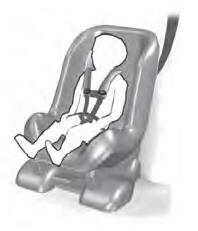
Child Seats

Use a child restraint (sometimes called an infant carrier, convertible seat, or toddler seat) for infants, toddlers and children weighing 40 lb (18 kg) or less (generally four-years-old or younger).
Using Lap and Shoulder Belts
WARNING: Do not place a rearward facing child restraint in front of an active airbag. Failure to follow this instruction could result in personal injury or death.
