
Lincoln Aviator: Parking Aids / Rear View Camera
WARNING: The rear view camera system is a reverse aid supplement device that still requires the driver to use it in conjunction with the interior and exterior mirrors for maximum coverage.
WARNING: Objects that are close to either corner of the bumper or under the bumper, might not be seen on the screen due to the limited coverage of the camera system.
WARNING: Reverse your vehicle slowly. Failure to follow this instruction could result in the loss of control of your vehicle, personal injury or death.
WARNING: Use caution when the rear cargo door is ajar. If the rear cargo door is ajar, the camera will be out of position and the video image could be incorrect. All guide lines disappear when the rear cargo door is ajar. Failure to follow this instruction could result in personal injury.
WARNING: Use caution when turning camera features on or off when the transmission is not in park (P). Make sure your vehicle is not moving.
Note: Some vehicles may not come equipped with guidelines.
The rear view camera system provides a video image of the area behind your vehicle.
During operation, lines appear in the display which represent your vehicle’s path and proximity to objects behind your vehicle.
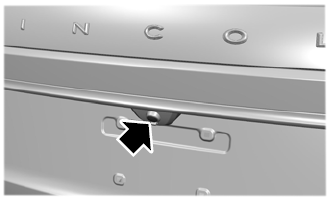
The camera is on the luggage compartment door.
- Using the Rear View Camera System
- Object Distance Indicator (If Equipped)
- Rear Camera On Demand (If Equipped)
- Manual Zoom
- Rear Camera Delay

 Using the Rear View Camera System
The rear view camera system displays what
is behind your vehicle when you place the
transmission in reverse (R).
Note: The reverse sensing system is not
effective at speeds above 3 mph (5 km/h)
and may not detect certain angular or
moving objects...
Other information:
Lincoln Aviator 2020-2026 Service Manual: Diagnosis and Testing - Pedestrian Alert System
Diagnostic Trouble Code (DTC) Chart Diagnostics in this manual assume a certain skill level and knowledge of Ford-specific diagnostic practices. REFER to: Diagnostic Methods (100-00 General Information, Description and Operation). Diagnostic Trouble Code Chart Module DTC Description Action PACM B1A01:01 Speaker #1: General Electrical Failure GO to Pinpoint Test C PACM B1A01:11 Speaker #1: Circuit Short To Ground GO to Pinpoint Test C PACM B1A01:12 Speaker #1: Circuit Short To Battery GO to Pinpoint Test D PACM B1A01:13 Speaker #1: Circuit Open GO to Pinpoint Test D PACM B1A02:01 Speaker #2: General Electrical Failure GO to Pinpoint Test C PACM B1A02:11 Speaker #2: Circuit Short To Ground GO to Pinpoint Test C PACM B1A02:12 Speaker #2: Circuit Short To Battery GO to Pinpoint Test D PACM B1A02:13 Speaker #2: Circuit Open GO to Pinpoint Test D PACM U0100:00 Lost Communication With ECM/PCM "A": No Sub Type Information GO to Pinpoint Test E PACM U0140:00 Lost Communication With Body Control Module: No Sub Type Information GO to Pinpoint Test F PACM U0422:00 Invalid Data Received From Body Control Module: No Sub Type Information GO to Pinpoint Test G PACM U201A:51 Control Module Main Calibration Data: Not Programmed GO to Pinpoint Test H PACM U2101:00 Control Module Configuration Incompatible: No Sub Type Information GO to Pinpoint Test H PACM U3000:41 Control Module: General Checksum Failure GO to Pinpoint Test I PACM U3000:42 Control Module: General Memory Failure GO to Pinpoint Test I PACM U3000:96 Control Module: Component Internal Failure GO to Pinpoint Test I PACM U3003:16 Battery Voltage: Circuit Voltage Below Threshold GO to Pinpoint Test J PACM U3003:17 Battery Voltage: Circuit Voltage Above Threshold GO to Pinpoint Test K Symptom Chart Diagnostics in this manual assume a certain skill level and knowledge of Ford-specific diagnostic practices...
Lincoln Aviator 2020-2026 Service Manual: General Procedures - Seatbelt Minder Deactivating/Activating
Activation WARNING: Before beginning any service procedure in this section, refer to Safety Warnings in section 100-00 General Information. Failure to follow this instruction may result in serious personal injury. NOTE: The driver and passenger seat Belt-Minder® deactivating/activating can be carried out using the scan tool...
Categories
- Manuals Home
- Lincoln Aviator Owners Manual
- Lincoln Aviator Service Manual
- Resetting the System
- Interior Lamps
- Description and Operation - Body and Frame
- New on site
- Most important about car
Locking and Unlocking the Doors from Inside
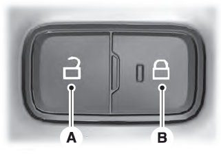
Locking the Doors
Press the lock switch on the door interior trim panel. The doors can no longer be released using the exterior door handle switches and the luggage compartment locks.
