Lincoln Aviator: Supplemental Climate Control / Description and Operation - Supplemental Climate Control - System Operation and Component Description
System Diagram
.jpg)
| Item | Description |
|---|---|
| 1 | SOBDMC |
| 2 | BCMC |
| 3 | PCM |
| 4 | Cabin Coolant Heater |
| 5 | Cabin heater coolant temperature sensor |
| 6 | Cabin heater coolant pump |
| 7 | Ambient Air Temperature (AAT) sensor |
| 8 | Engine Coolant Temperature (ECT) sensor |
Network Message Chart - Module Network Input Messages - SOBDMC Cabin Coolant Heater
| Broadcast Message | Originating Module | Message Purpose |
|---|---|---|
| Engine Coolant Temperature Data | PCM | This message contains raw value from the engine coolant temperature sensor. |
| Ambient air temperature filtered | PCM | This message contains filtered value from the ambient air temperature sensor. |
System Operation
Cabin Coolant Heater System
The cabin coolant heater system provides warm coolant to the heater core to warm the passenger compartment whenever the front DATC module requests heat and the vehicle is in a driving mode, remote started, or doing Cabin Drive-Conditioning.
A SOBDMC controlled cabin coolant heater warms the coolant.
The cabin heater coolant diverter valve allows two modes: Either an isolated coolant loop with cabin coolant heater, heater core, and cabin heater coolant pump or a combined loop of those components along with the engine and other coolant components.
A cabin heater coolant temperature sensor in the cabin heater system provides the PCM with coolant temperature information.
Component Description
Cabin Heater Coolant Pump
The cabin heater coolant pump is controlled by the PCM and provides coolant to the cabin coolant heater system while the vehicle is in a driving mode, remote started, or doing Cabin Drive-Conditioning.
Cabin Coolant Heater ( PTC Heater) ( PHEV only)
The cabin coolant heater has both low voltage and high voltage electrical connections. The low voltage circuits are used for controlling the unit, while the high voltage circuits are used for heating the coolant. The cabin coolant heater uses electricity, or more accurately, the heat for resistance in electrical circuits to quickly raise the temperature of the coolant to normal operating temperature. The SOBDMC sends power to the cabin coolant heater and controls the PWM circuit to the heater.
Cabin Heater Coolant Temperature Sensor (PTC Heater) ( PHEV only)
The cabin heater coolant temperature sensor is connected to the PCM. The sensor provides the coolant temperature information to the PCM.
Heater Core
The heater core consists of fins and tubes arranged to extract heat from the engine coolant and transfer the heat to air passing through the plenum.
Cabin Heater Coolant Diverter Valve
The default state of the cabin heater coolant diverter valve is de-energized, placing the system in combined loop mode. Coolant flows out of the engine, then back, in the following order:
- cabin heater coolant pump
- cabin coolant heater
- cabin heater coolant temperature sensor
- heater core
- cabin heater coolant diverter valve
- thermostat housing
- main electric water pump
When energized by the PCM the cabin heater coolant diverter valve places the system into the isolated loop mode. Coolant flows out of the valve, then back, in the following order:
- cabin heater coolant pump
- cabin coolant heater
- cabin heater coolant temperature sensor
- heater core
 Description and Operation - Supplemental Climate Control - Overview
Overview
The cabin coolant heater system provides warm coolant to the heater core to warm the passenger compartment whenever the front DATC module requests heat and the HEV is in a driving mode, remote started, or doing Cabin Drive Conditioning...
 Removal and Installation - Cabin Coolant Heater
Removal
NOTE:
Removal steps in this procedure may contain installation details.
With the vehicle in NEUTRAL, position it on a hoist.
Refer to: Jacking and Lifting (100-02 Jacking and Lifting, Description and Operation)...
Other information:
Lincoln Aviator 2020-2026 Service Manual: Description and Operation - Charging System - Overview
Overview The generator is driven by the FEAD belt. When the engine is started, the generator begins to generate AC voltage which is internally converted to DC voltage. The DC voltage level is controlled by the voltage regulator (located on the rear of the generator) and is supplied to the battery...
Lincoln Aviator 2020-2026 Owners Manual: Navigation Map Accuracy and Updates
HERE is the digital map provider for the navigation application. If you find map data errors, you may report them directly to HERE by going to www.here.com. HERE evaluates all reported map errors and responds with the result of their investigation by e-mail...
Categories
- Manuals Home
- Lincoln Aviator Owners Manual
- Lincoln Aviator Service Manual
- Opening and Closing the Hood
- Interior Lamps
- Locking and Unlocking
- New on site
- Most important about car
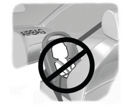
Children and Airbags
WARNING: Airbags can kill or injure a child in a child restraint. Never place a rear-facing child restraint in front of an active airbag. If you must use a forward-facing child restraint in the front seat, move the seat upon which the child restraint is installed all the way back.


.jpg)