Lincoln Aviator 2020-2026 Service Manual / Electrical / Climate Control System / Supplemental Climate Control / Removal and Installation - Cabin Coolant Heater
Lincoln Aviator: Supplemental Climate Control / Removal and Installation - Cabin Coolant Heater
Removal
NOTE: Removal steps in this procedure may contain installation details.
-
With the vehicle in NEUTRAL, position it on a hoist.
Refer to: Jacking and Lifting (100-02 Jacking and Lifting, Description and Operation).
-
Disconnect the batteries.
Refer to: Battery Disconnect and Connect (414-01 Battery, Mounting and Cables, General Procedures).
-
Drain the cooling system.
Refer to: Engine Cooling System Draining, Vacuum Filling and Bleeding (303-03A Engine Cooling - 3.0L EcoBoost, General Procedures).
-
Remove the front bumper cover.
Refer to: Front Bumper Cover (501-19 Bumpers, Removal and Installation).
-
-
Disconnect the electrical connectors.
-
Detach the wiring harness routing clips.
-
Remove the ground wire retainer and position aside the wiring harness.
Torque: 106 lb.in (12 Nm)
-
Disconnect the electrical connectors.
.jpg) |
-
-
Disconnect the coolant hoses.
-
Detach the coolant hose routing clips.
-
Remove the retainers and the cabin coolant heater.
Torque: 26 lb.ft (35 Nm)
-
Disconnect the coolant hoses.
.jpg) |
Installation
-
To install, reverse the removal procedure.
-
Fill and bleed the cooling system.
Refer to: Engine Cooling System Draining, Vacuum Filling and Bleeding (303-03A Engine Cooling - 3.0L EcoBoost, General Procedures).
 Description and Operation - Supplemental Climate Control - System Operation and Component Description
System Diagram
Item
Description
1
SOBDMC
2
BCMC
3
PCM
4
Cabin Coolant Heater
5
Cabin heater coolant temperature sensor
6
Cabin heater coolant pump
7
Ambient Air Temperature (AAT) sensor
8
Engine Coolant Temperature (ECT) sensor
Network Message Chart - Module Network Input Messages - SOBDMC Cabin Coolant Heater
Broadcast Message
Originating Module
Message Purpose
Engine Coolant Temperature Data
PCM
This message contains raw value from the engine coolant temperature sensor...
 Removal and Installation - Cabin Heater Coolant Diverter Valve
Special Tool(s) /
General Equipment
Hose Clamp(s)
Hose Clamp Remover/Installer
Fluid Container
Removal
NOTE:
Removal steps in this procedure may contain installation details...
Other information:
Lincoln Aviator 2020-2026 Service Manual: Removal and Installation - Intake Manifold
Removal NOTICE: During engine repair procedures, cleanliness is extremely important. Any foreign material, including any material created while cleaning gasket surfaces, that enters the oil passages, coolant passages or the oil pan, can cause engine failure...
Lincoln Aviator 2020-2026 Service Manual: Description and Operation - Pyrotechnic Device Health and Safety Precautions
WARNING: Service and handling of Pyrotechnic Components is restricted to qualified personnel. The required qualifications vary by region. Always observe local laws and legislative directives regarding Pyrotechnic Components service and handling...
Categories
- Manuals Home
- Lincoln Aviator Owners Manual
- Lincoln Aviator Service Manual
- Anti-Theft Alarm
- Garage Door Opener
- Child Safety Locks
- New on site
- Most important about car
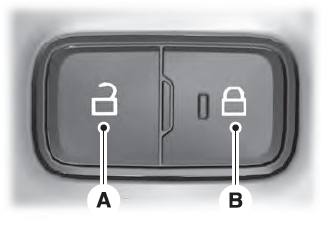
Locking and Unlocking the Doors from Inside

Locking the Doors
Press the lock switch on the door interior trim panel. The doors can no longer be released using the exterior door handle switches and the luggage compartment locks.
Copyright © 2026 www.liaviator2.com
