Lincoln Aviator: Exterior Lighting / Diagnosis and Testing - Autolamps
Diagnostic Trouble Code (DTC) Chart
Diagnostics in this manual assume a certain skill level and knowledge of Ford-specific diagnostic practices.
REFER to: Diagnostic Methods (100-00 General Information, Description and Operation).
Diagnostic Trouble Code Chart
| Module | DTC | Description | Action |
|---|---|---|---|
| BCM | B1A85:11 | Ambient Light Sensor: Circuit Short To Ground | GO to Pinpoint Test A |
| BCM | B1A85:13 | Ambient Light Sensor:Circuit Open | GO to Pinpoint Test A |
| BCM | — | All other BCM Diagnostic Trouble Codes (DTCs) |
REFER to: Body Control Module (BCM) (419-10 Multifunction Electronic Modules, Diagnosis and Testing). |
Symptom Charts
Symptom Chart: Autolamps
Diagnostics in this manual assume a certain skill level and knowledge of Ford-specific diagnostic practices.
REFER to: Diagnostic Methods (100-00 General Information, Description and Operation).
| Condition | Possible Sources | Actions |
|---|---|---|
| A module does not respond to the diagnostic scan tool |
|
REFER to: Communications Network (418-00 Module Communications Network, Diagnosis and Testing). |
| The autolamps are inoperative or do not operate correctly | Refer to the Pinpoint Test | GO to Pinpoint Test A |
Pinpoint Tests
.jpg) PINPOINT TEST A : THE AUTOLAMPS ARE INOPERATIVE OR DO NOT OPERATE CORRECTLY
PINPOINT TEST A : THE AUTOLAMPS ARE INOPERATIVE OR DO NOT OPERATE CORRECTLY|
Refer to Wiring Diagrams Cell 86 for schematic and connector information. Normal Operation and Fault Conditions
REFER to: Exterior Lighting - Overview (417-01 Exterior Lighting, Description and Operation). DTC Fault Trigger Conditions
Possible Sources
Visual Inspection and Pre-checks
|
||||||||||
| A1 CHECK THE MANUAL HEADLAMP OPERATION | ||||||||||
Do the headlamps operate correctly?
|
||||||||||
| A2 CHECK FOR VOLTAGE TO THE LIGHT SENSOR | ||||||||||
Is the voltage approximately 5 volts?
|
||||||||||
| A3 CHECK THE LIGHT SENSOR FOR GROUND | ||||||||||
Is the voltage approximately 5 volts?
|
||||||||||
| A4 CHECK THE LIGHT SENSOR GROUND CIRCUIT FOR AN OPEN | ||||||||||
Is the resistance less than 3 ohms?
|
||||||||||
| A5 CHECK THE LIGHT SENSOR INPUT CIRCUIT FOR A SHORT TO GROUND | ||||||||||
Is the resistance greater than 10,000 ohms?
|
||||||||||
| A6 CHECK THE LIGHT SENSOR INPUT CIRCUIT FOR AN OPEN | ||||||||||
Is the resistance less than 3 ohms?
|
||||||||||
| A7 CHECK THE LIGHT SENSOR INPUT CIRCUIT FOR A SHORT TO VOLTAGE | ||||||||||
Is any voltage present?
|
||||||||||
| A8 CHECK FOR CORRECT BCM (BODY CONTROL MODULE) OPERATION | ||||||||||
Is the concern still present?
|
 Description and Operation - Exterior Lighting - System Operation and Component Description
System Operation
Headlamps - Low Series
System Diagram
Item
Description
1
HS-CAN2
2
BCM
3
LH low beam
4
LH high beam
5
RH low beam
6
RH high beam
7
SCCM
8
LH steering column multifunction switch
9
IPMA
10
GWM
11
HS-CAN1
12
Start/Stop switch
13
HCM
14
LIN
15
LIN
16
PCM
17
LH headlamp
18
RH headlamp
19
LH front suspension height sensor
20
LH rear suspension height sensor
21
Headlamp switch
22
(If equipped automatic headlamp leveling)
23
LIN
24
LIN
Network Message Chart
BCM Network Input Messages
Broadcast Message
Originating Module
Message Purpose
Headlamp flash to pass status
GWM
Indicates to the BCM a request for the high beams or flash-to-pass...
 Diagnosis and Testing - Daytime Running Lamps (DRL)
Symptom Charts
Symptom Chart: DRL
Diagnostics in this manual assume a certain skill level and knowledge of Ford-specific diagnostic practices. REFER to: Diagnostic Methods (100-00 General Information, Description and Operation)...
Other information:
Lincoln Aviator 2020-2026 Service Manual: Removal and Installation - Front Seat Backrest Blower Motor
Removal NOTE: Driver seat shown, passenger seat similar. Remove the front seat. Refer to: Front Seat (501-10A Front Seats, Removal and Installation). Remove the front seat backrest panel. Refer to: Front Seat Backrest Panel (501-10A Front Seats, Removal and Installation)...
Lincoln Aviator 2020-2026 Service Manual: General Procedures - Air Conditioning (A/C) System Flushing - Vehicles With: R134A Refrigerant
Special Tool(s) / General Equipment Air Conditioning Flush and Purge Service Unit Air Conditioning Adaptor Kit Materials Name Specification Motorcraft® A/C System Flushing SolventYN-23 - Flushing NOTICE: Use the Refrigerant Identification Equipment before recovering any of the vehicle's refrigerant...
Categories
- Manuals Home
- Lincoln Aviator Owners Manual
- Lincoln Aviator Service Manual
- Locking and Unlocking
- Fuel Quality
- Interior Lamps
- New on site
- Most important about car
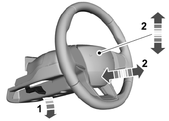
Adjusting the Steering Wheel - Vehicles With: Manual Adjustable Steering Column
WARNING: Do not adjust the steering wheel when your vehicle is moving.
Note: Make sure that you are sitting in the correct position.
Unlock the steering column. Adjust the steering wheel to the desired position.

.jpg) PINPOINT TEST A : THE AUTOLAMPS ARE INOPERATIVE OR DO NOT OPERATE CORRECTLY
PINPOINT TEST A : THE AUTOLAMPS ARE INOPERATIVE OR DO NOT OPERATE CORRECTLY.jpg)
.jpg)