Lincoln Aviator: Driveshaft / Disassembly and Assembly - Driveshaft Alignment Bushing
Special Tool(s) / General Equipment
| Three Leg Puller | |
| Punch | |
| Copper Hammer | |
| Vise |
Materials
| Name | Specification |
|---|---|
| Motorcraft® Premium Long-Life Grease XG-1-E1 |
ESA-M1C75-B |
DISASSEMBLY
-
Remove the rear driveshaft.
Refer to: Rear Driveshaft (205-01 Driveshaft, Removal and Installation).
-
Remove the driveshaft flexible coupling.
Refer to: Driveshaft Flexible Coupling (205-01 Driveshaft, Removal and Installation).
-
Using the general equipments, remove and discard the driveshaft alignment bushing.
Use the General Equipment: Vise
Use the General Equipment: Copper Hammer
Use the General Equipment: Punch
.jpg) |
ASSEMBLY
-
NOTICE: Do not over-lubricate the driveshaft components. Using excessive grease may damage the driveshaft components.
NOTE: Wipe off any excess grease.
Clean and lubricate the driveshaft flange at alignment bushing mating surface.
Use the General Equipment: Vise
Material: Motorcraft® Premium Long-Life Grease / XG-1-E1 (ESA-M1C75-B)
.jpg) |
-
NOTE: Make sure that new components are installed.
NOTE: Make sure that the rubber seal end of the bushing is facing outward.
NOTE: Press the component by hand initially.
Position the driveshaft alignment bushing into the driveshaft.
.jpg) |
-
Using the general equipments, press-in the new
driveshaft alignment bushing until it has bottomed out inside of the
driveshaft flange.
Use the General Equipment: Vise
Use the General Equipment: Three Leg Puller
.jpg) |
-
Ensure the final press in height of the new driveshaft alignment bushing should be 16 mm as shown.
.jpg) |
-
NOTICE: Do not over-lubricate the driveshaft components. Using excessive grease may damage the driveshaft components.
NOTE: Wipe off any excess grease.
Lubricate the driveshaft alignment bushing cavity with grease before installing the driveshaft.
Material: Motorcraft® Premium Long-Life Grease / XG-1-E1 (ESA-M1C75-B)
.jpg) |
-
Install the driveshaft flexible coupling.
Refer to: Driveshaft Flexible Coupling (205-01 Driveshaft, Removal and Installation).
-
Install the rear driveshaft.
Refer to: Rear Driveshaft (205-01 Driveshaft, Removal and Installation).
 Removal and Installation - Rear Driveshaft Slip Yoke Boot
Special Tool(s) /
General Equipment
Crimping Tool
Materials
Name
Specification
Motorcraft® Premium Long-Life GreaseXG-1-E1
ESA-M1C75-B
Removal
Remove the rear driveshaft...
 Disassembly and Assembly - Driveshaft Center Bearing
Special Tool(s) /
General Equipment
Hydraulic Press
Bearing Separator
Materials
Name
Specification
Motorcraft® Premium Long-Life GreaseXG-1-E1
ESA-M1C75-B
DISASSEMBLY
Remove the rear driveshaft slip yoke boot...
Other information:
Lincoln Aviator 2020-2026 Owners Manual: Transmission Operation. Battery
Transmission Operation The engine and electric motor together propel the vehicle through the automatic transmission. This is normal hybrid operating and helps deliver fuel efficiency and performance. Battery Your hybrid is equipped with a high voltage battery...
Lincoln Aviator 2020-2026 Service Manual: General Procedures - Electronic Leak Detection - Vehicles With: R134A Refrigerant
Special Tool(s) / General Equipment Electronic Leak Detector Inspection NOTE: Use a Rotunda-approved Electronic Leak Detector for R-134a refrigerant SAE Certified to J2791. NOTE: Good ventilation is necessary in the area where electronic A/C leak testing is to be carried out...
Categories
- Manuals Home
- Lincoln Aviator Owners Manual
- Lincoln Aviator Service Manual
- Fuel Quality
- Body and Paint
- Disabling Auto-Start-Stop
- New on site
- Most important about car
Child Safety Locks
When the child safety locks are set, you cannot open the rear doors from the inside.

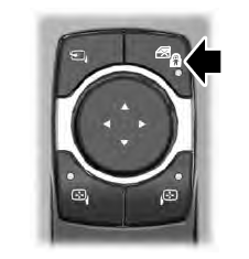
The child safety lock control is on the driver door.
Press the control to switch the child safety locks on. Press the control again to switch them off. A light on the child safety control illuminates when you switch them on.
