Lincoln Aviator: Driveshaft / Disassembly and Assembly - Driveshaft Center Bearing
Special Tool(s) / General Equipment
| Hydraulic Press | |
| Bearing Separator |
Materials
| Name | Specification |
|---|---|
| Motorcraft® Premium Long-Life Grease XG-1-E1 |
ESA-M1C75-B |
DISASSEMBLY
-
Remove the rear driveshaft slip yoke boot.
Refer to: Rear Driveshaft Slip Yoke Boot (205-01 Driveshaft, Removal and Installation).
-
NOTE: The heat shield is to be reused unless damaged.
NOTE: Note the position of component before removal.
NOTE: This step is only necessary if replacing the center bearing.
If equipped.
Drill out the rivets and remove the heat shield from the center bearing. Discard the rivets.
.jpg) |
-
NOTE: To avoid component damage, do not clamp on the driveshaft tube.
NOTE: Take extra care not to damage the component.
Using the general equipments, remove the center bearing from the driveshaft.
Use the General Equipment: Bearing Separator
Use the General Equipment: Hydraulic Press
.jpg) |
ASSEMBLY
-
NOTICE: Do not over-lubricate the driveshaft components. Using excessive grease may damage the driveshaft components.
NOTE: Wipe off any excess grease.
Clean and lubricate the center bearing mating surface with grease.
Material: Motorcraft® Premium Long-Life Grease / XG-1-E1 (ESA-M1C75-B)
.jpg) |
-
NOTE: The center bearing is serviced as a complete assembly.
Press the new center bearing assembly onto the spline yoke until it is seated against the machined shoulder.
Use the General Equipment: Hydraulic Press
.jpg) |
-
NOTICE: Do not over-lubricate the driveshaft components. Using excessive grease may damage the driveshaft components.
NOTE: Wipe off any excess grease.
Wipe off any excess grease from the splines and boot groove.
Material: Motorcraft® Premium Long-Life Grease / XG-1-E1 (ESA-M1C75-B)
.jpg) |
-
Install the rear driveshaft slip yoke boot.
Refer to: Rear Driveshaft Slip Yoke Boot (205-01 Driveshaft, Removal and Installation).
-
NOTE: Make sure that the components are installed to the position noted before removal.
If removed.
Attach the center bearing heat shield and install the new rivets.
.jpg) |
 Disassembly and Assembly - Driveshaft Alignment Bushing
Special Tool(s) /
General Equipment
Three Leg Puller
Punch
Copper Hammer
Vise
Materials
Name
Specification
Motorcraft® Premium Long-Life GreaseXG-1-E1
ESA-M1C75-B
DISASSEMBLY
Remove the rear driveshaft...
 Disassembly and Assembly - Driveshaft Universal Joint
Special Tool(s) /
General Equipment
205-086
(T74P-4635-C)
Installer/Remover, C-Frame and Screw
Materials
Name
Specification
Motorcraft® Premium Long-Life GreaseXG-1-E1
ESA-M1C75-B
DISASSEMBLY
NOTICE:
Do not, under any circumstance, clamp the driveshaft
assembly in the jaws of a vise or similar holding fixture...
Other information:
Lincoln Aviator 2020-2026 Service Manual: Removal and Installation - Rear Heating, Ventilation and Air Conditioning (RHVAC) Control Module
Special Tool(s) / General Equipment Interior Trim Remover Removal NOTE: Removal steps in this procedure may contain installation details. Release the clips and position aside the side panel consoles. Use the General Equipment: Interior Trim Remover Release the clips and position aside the upper side panel consoles...
Lincoln Aviator 2020-2026 Owners Manual: The Better Business Bureau (BBB) Auto Line Program (U.S. Only)
Your satisfaction is important to Ford Motor Company and to your dealer. If a warranty concern has not been resolved using the three-step procedure outlined earlier in this chapter in the Getting the Services you need section, you may be eligible to participate in the BBB AUTO LINE program...
Categories
- Manuals Home
- Lincoln Aviator Owners Manual
- Lincoln Aviator Service Manual
- Anti-Theft Alarm
- Body and Paint
- Garage Door Opener
- New on site
- Most important about car
Remote Control
Passive Key

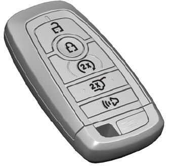
The passive key operates the power locks and the remote start system. The passive key must be in your vehicle to use the push button start.
Note: You may not be able to shift out of park (P) unless the passive key is inside your vehicle.
