
Lincoln Aviator: Appendices / Electromagnetic Compatibility
WARNING: Do not place objects or mount equipment on or near the airbag cover, on the side of the front or rear seatbacks, or in areas that may come into contact with a deploying airbag. Failure to follow these instructions may increase the risk of personal injury in the event of a crash.
WARNING: Do not fasten antenna cables to vehicle wiring, fuel pipes and brake pipes.
WARNING: Keep antenna and power cables at least 4 in (10 cm) from any electronic modules and airbags.
Note: We test and certify your vehicle to meet electromagnetic compatibility legislation. It is your responsibility to make sure that any equipment an authorized dealer installs on your vehicle complies with applicable local legislation and other requirements. Installation of some aftermarket electronic devices could degrade the performance of vehicle functions, which use radio frequency signals such as broadcast radio receiver, tire pressure monitoring system, push button start, Bluetooth connectivity or satellite navigation.
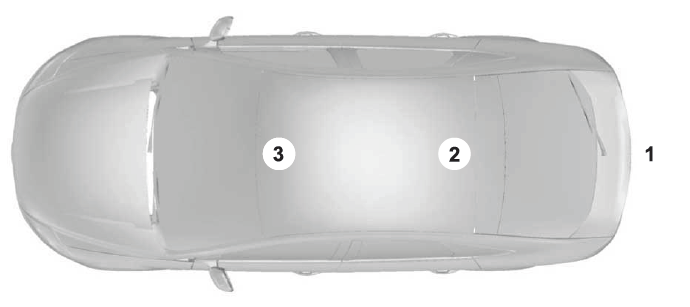
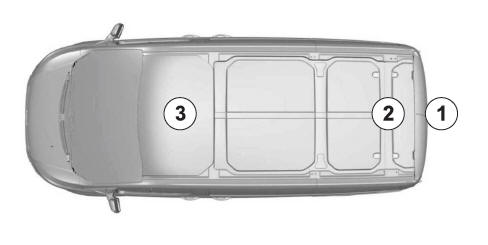
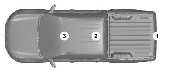
Note: Any radio frequency transmitter equipment in your vehicle (such as cellular telephones and amateur radio transmitters) must keep to the parameters in the following illustrations and table. We do not provide any other special provisions or conditions for installations or use.
Car/SUV
Van
Truck


 Appendices
..
 End User License Agreement
VEHICLE SOFTWARE END USER
LICENSE AGREEMENT (EULA)
You (“You” or “Your” as applicable) have
acquired a vehicle having several
devices, including SYNC ® and various
control modules, ("DEVICES") that include
software licensed or owned by Ford
Motor Company and its affiliates ("FORD
MOTOR COMPANY")...
Other information:
Lincoln Aviator 2020-2026 Service Manual: Description and Operation - Impact of Insufficient Repair Quality
Body repairs usually require a significant level of intervention in the existing body shell structure. The corrosion protection, seals and NVH components are destroyed and must be replaced. To prevent the vehicle quality from being compromised due to a poor quality repair, all repairs must be inspected during and after the accident repair...
Lincoln Aviator 2020-2026 Service Manual: Diagnosis and Testing - Parking Aid
Diagnostic Trouble Code (DTC) Chart Diagnostics in this manual assume a certain skill level and knowledge of Ford-specific diagnostic practices. REFER to: Diagnostic Methods (100-00 General Information, Description and Operation). Diagnostic Trouble Code Chart Module DTC Description Action IPMB B129C:08 Left Front Side Sensor: Bus Signal / Message Failure GO to Pinpoint Test A IPMB B129C:96 Left Front Side Sensor: Component Internal Failure GO to Pinpoint Test E IPMB B129C:98 Left Front Side Sensor: Component or System Over Temperature GO to Pinpoint Test F IPMB B129D:08 Right Front Side Sensor: Bus Signal / Message Failure GO to Pinpoint Test B IPMB B129D:96 Right Front Side Sensor: Component Internal Failure GO to Pinpoint Test E IPMB B129D:98 Right Front Side Sensor: Component or System Over Temperature GO to Pinpoint Test F IPMB B13F3:08 Left Rear Side Sensor: Bus Signal / Message Failure GO to Pinpoint Test C IPMB B13F3:96 Left Rear Side Sensor: Component Internal Failure GO to Pinpoint Test G IPMB B13F3:98 Left Rear Side Sensor: Component or System Over Temperature GO to Pinpoint Test F IPMB B13F4:08 Right Rear Side Sensor: Bus Signal / Message Failure GO to Pinpoint Test D IPMB B13F4:96 Right Rear Side Sensor: Component Internal Failure GO to Pinpoint Test G IPMB B13F4:98 Right Rear Side Sensor: Component or System Over Temperature GO to Pinpoint Test F Symptom Chart(s) Diagnostics in this manual assume a certain skill level and knowledge of Ford-specific diagnostic practices...
Categories
- Manuals Home
- Lincoln Aviator Owners Manual
- Lincoln Aviator Service Manual
- Garage Door Opener
- Changing the Front Wiper Blades - Vehicles With: Heated Wiper Blades
- Disabling Auto-Start-Stop
- New on site
- Most important about car
Child Seats
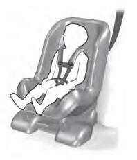
Use a child restraint (sometimes called an infant carrier, convertible seat, or toddler seat) for infants, toddlers and children weighing 40 lb (18 kg) or less (generally four-years-old or younger).
Using Lap and Shoulder Belts
WARNING: Do not place a rearward facing child restraint in front of an active airbag. Failure to follow this instruction could result in personal injury or death.
