
Lincoln Aviator: Engine Cooling - 3.0L EcoBoost / General Procedures - Engine Cooling System Draining, Vacuum Filling and Bleeding
Special Tool(s) / General Equipment
.jpg) |
ROB75240 Coolant/Battery Refractometer (Fahrenheit) |
| Fluid Container | |
| Cooling System Vacuum Tester and Refiller | |
Draining
NOTICE: The coolant must be recovered in a suitable, clean container for reuse. If the coolant is contaminated, it must be recycled or disposed of correctly. Using contaminated coolant may result in damage to the engine or cooling system components.
NOTICE: Use the correct coolant. Do not mix coolant types. Mixing coolant types may degrade the coolant corrosion protection and may damage the engine or cooling system. For the correct coolant specified for this vehicle, refer to Specifications.
NOTICE: Always fill the cooling system with the manufacturer's specified coolant. Chemically flush the cooling system if a non-specified coolant has been used. Refer to Cooling System Flushing. Failure to follow these instructions may damage the engine or cooling system.
NOTE: During normal vehicle operation, coolant can change color. As long as the engine coolant is clear and uncontaminated, this color change does not indicate the engine coolant has degraded nor does it require the engine coolant to be drained, the system to be flushed, or the engine coolant to be replaced.
NOTE: Less than 80% of coolant capacity can be recovered with the engine in the vehicle. Dirty, rusty or contaminated coolant requires replacement.
-
.jpg)
.jpg)
Remove the pressure relief cap..jpg) WARNING:
When releasing the cooling system pressure, cover the coolant expansion tank cap with a thick cloth.
WARNING:
When releasing the cooling system pressure, cover the coolant expansion tank cap with a thick cloth.
.jpg) |
-
With the vehicle in NEUTRAL, position it on a hoist.
Refer to: Jacking and Lifting (100-02 Jacking and Lifting, Description and Operation).
-
Remove the retainers and the engine underbodyshield.
.jpg) |
-
Release the clip and position the radiator air deflector aside.
.jpg) |
-
Connect a hose to drain the coolant. Open the radiator drain valve and drain the engine coolant in a suitable, clean container.
WARNING:
Be prepared to collect escaping fluid.
Use the General Equipment: Fluid Container
.jpg) |
Filling
Filling and Bleeding with a Vacuum Cooling System Filler
-
-
NOTICE: Use the correct coolant. Do not mix coolant types. Mixing coolant types may degrade the coolant corrosion protection and may damage the engine or cooling system. For the correct coolant specified for this vehicle, refer to Specifications.
NOTICE: Engine coolant provides boil protection, corrosion protection, freeze protection, and cooling efficiency to the engine and cooling components. In order to obtain these protections, maintain the engine coolant at the correct concentration and fluid level in the degas bottle.
NOTICE: Do not add alcohol, methanol, or brine, or any engine coolants mixed with alcohol or methanol antifreeze. These can cause engine damage from overheating or freezing.
NOTE: Ford Motor Company does NOT recommend the use of recycled engine coolant since a Ford-approved recycling process is not yet available.
When adding or topping off the engine coolant:
-
Measure the coolant concentration in the vehicle.
Use Special Service Tool: ROB75240 Coolant/Battery Refractometer (Fahrenheit).
-
Determine the concentration desired based on the
vehicle duty cycle of extreme hot or cold operating conditions.
-
Add, top-off or adjust the coolant to the correct concentration.
Refer to: Specifications (303-03A Engine Cooling - 3.0L EcoBoost, Specifications).
-
-
Close the radiator drain valve.
.jpg) |
-
Position the radiator air deflector and install the clip.
|
-
Install the engine underbodyshield and the retainers.
|
-
Install the vacuum cooling system filler and follow
the manufacturer's instructions to fill and bleed the system.
Use the General Equipment: Cooling System Vacuum Tester and Refiller
-
Fill the degas bottle to the MAX FILL line.
-
Install the degas bottle cap until it contacts the hard stop.
-
Turn the climate control system off.
-
Start the engine and increase the engine speed to 3,500 rpm and hold for 30 seconds.
-
Turn the engine off and wait for 1 minute to purge any large air pockets from the cooling system.
-
Check the engine coolant level in the degas bottle and if necessary fill to the top of the MAX FILL line on the degas bottle.
WARNING:
Always allow the engine to cool before opening
the cooling system. Do not unscrew the coolant pressure relief cap when
the engine is operating or the cooling system is hot. The cooling system
is under pressure; steam and hot liquid can come out forcefully when
the cap is loosened slightly. Failure to follow these instructions may
result in serious personal injury.
-
Start the engine and let it idle until the engine
reaches normal operating temperature and the thermostat is fully open. A
fully open thermostat is verified by the cooling fan cycling on at
least once.
-
Increase the engine speed to 3,500 rpm and hold for 30 seconds.
-
Allow the engine to idle for 30 seconds.
-
Turn the engine off for 1 minute.
-
Repeat steps 13 through 15 a total of 10 times to remove any remaining air trapped in the system.
-
Check the engine coolant level in the degas bottle and, if necessary, fill to the top of the MAX FILL line on the degas bottle.
WARNING:
Always allow the engine to cool before opening
the cooling system. Do not unscrew the coolant pressure relief cap when
the engine is operating or the cooling system is hot. The cooling system
is under pressure; steam and hot liquid can come out forcefully when
the cap is loosened slightly. Failure to follow these instructions may
result in serious personal injury.
-
Install the pressure relief cap until it contacts the hard stop.
.jpg) |
Filling and Bleeding without a Vacuum Cooling System Filler
-
-
NOTICE: Use the correct coolant. Do not mix coolant types. Mixing coolant types may degrade the coolant corrosion protection and may damage the engine or cooling system. For the correct coolant specified for this vehicle, refer to Specifications.
NOTICE: Engine coolant provides boil protection, corrosion protection, freeze protection, and cooling efficiency to the engine and cooling components. In order to obtain these protections, maintain the engine coolant at the correct concentration and fluid level in the degas bottle.
NOTICE: Do not add alcohol, methanol, or brine, or any engine coolants mixed with alcohol or methanol antifreeze. These can cause engine damage from overheating or freezing.
NOTE: Ford Motor Company does NOT recommend the use of recycled engine coolant since a Ford-approved recycling process is not yet available.
When adding or topping off the engine coolant:
-
Measure the coolant concentration in the vehicle.
Use Special Service Tool: ROB75240 Coolant/Battery Refractometer (Fahrenheit).
-
Determine the concentration desired based on the
vehicle duty cycle of extreme hot or cold operating conditions.
-
Add, top-off or adjust the coolant to the correct concentration.
Refer to: Specifications (303-03A Engine Cooling - 3.0L EcoBoost, Specifications).
-
-
Close the radiator drain valve.
|
-
Position the radiator air deflector and install the clip.
|
-
Install the engine underbodyshield and the retainers.
|
-
Fill the degas bottle to the MAX FILL line.
-
Install the degas bottle cap until it contacts the hard stop.
-
Turn the climate control system off.
-
Start the engine and increase the engine speed to 3,500 rpm and hold for 30 seconds.
-
Turn the engine off and wait for 1 minute to purge any large air pockets from the cooling system.
-
Check the engine coolant level in the degas bottle and if necessary fill to the top of the MAX FILL line on the degas bottle.
WARNING:
Always allow the engine to cool before opening
the cooling system. Do not unscrew the coolant pressure relief cap when
the engine is operating or the cooling system is hot. The cooling system
is under pressure; steam and hot liquid can come out forcefully when
the cap is loosened slightly. Failure to follow these instructions may
result in serious personal injury.
-
Start the engine and let it idle until the engine
reaches normal operating temperature and the thermostat is fully open. A
fully open thermostat is verified by the cooling fan cycling on at
least once.
-
Increase the engine speed to 3,500 rpm and hold for 30 seconds.
-
Allow the engine to idle for 30 seconds.
-
Turn the engine off for 1 minute.
-
Repeat steps 30 through 32 a total of 10 times to remove any remaining air trapped in the system.
-
Check the engine coolant level in the degas bottle and, if necessary, fill to the top of the MAX FILL line on the degas bottle.
WARNING:
Always allow the engine to cool before opening
the cooling system. Do not unscrew the coolant pressure relief cap when
the engine is operating or the cooling system is hot. The cooling system
is under pressure; steam and hot liquid can come out forcefully when
the cap is loosened slightly. Failure to follow these instructions may
result in serious personal injury.
-
Select the maximum heater temperature and blower
motor speed settings. Position the control to discharge air at A/C vents
in instrument panel.
-
Start the engine and allow to idle. While engine is idling, feel for hot air at A/C vents.
-
NOTICE: If the air discharge remains cool and the Engine Coolant Temperature gauge does not move, the engine coolant level is low and must be filled. Stop the engine, allow the engine to cool and fill cooling system. Failure to follow these instructions may result in damage to the engine.
Start the engine and allow it to idle until normal operating temperature is reached. Hot air should discharge from A/C vents. The Engine Coolant Temperature (ECT) gauge should maintain a stabilized reading in the middle of the NORMAL range. The upper radiator hose should feel hot to the touch.
-
Shut the engine off and allow the engine to cool.
-
Check the engine coolant level in the degas bottle and fill as necessary.
-
Repeat the previous 4 steps as necessary.
-
Install the pressure relief cap until it contacts the hard stop.
|
 Diagnosis and Testing - Engine Temperature
Diagnostic Trouble Code (DTC) Chart
Diagnostics in this manual assume a certain skill level and knowledge of Ford-specific diagnostic practices.REFER to: Diagnostic Methods (100-00 General Information, Description and Operation)...
 General Procedures - Engine Cooling System Flushing
Materials
Name
Specification
Motorcraft® Premium Cooling System FlushVC-1
ESR-M14P7-A
Flushing
WARNING:
Always allow the engine to cool before opening the cooling
system...
Other information:
Lincoln Aviator 2020-2026 Service Manual: Removal and Installation - Hands-Free Liftgate Actuation Lower Sensor
Removal NOTE: Removal steps in this procedure may contain installation details. Remove the rear bumper cover. Refer to: Rear Bumper Cover (501-19 Bumpers, Removal and Installation). Remove the following items: Disconnect the hands-free liftgate actuation lower sensor electrical connector...
Lincoln Aviator 2020-2026 Service Manual: Description and Operation - Diagnostic Methods
This document provides critical diagnostic knowledge required for successful repair outcomes. It identifies technical competencies expected by users of this manual. Ford Diagnostic Assumptions Ford diagnostics assume the vehicle concern described by the test title is currently present...
Categories
- Manuals Home
- Lincoln Aviator Owners Manual
- Lincoln Aviator Service Manual
- Drive Modes
- Interior Lamps
- Keyless Entry
- New on site
- Most important about car
Child Safety Locks
When the child safety locks are set, you cannot open the rear doors from the inside.
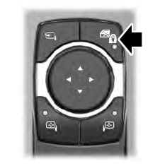
The child safety lock control is on the driver door.
Press the control to switch the child safety locks on. Press the control again to switch them off. A light on the child safety control illuminates when you switch them on.
