
Lincoln Aviator: Engine System - General Information / General Procedures - Piston Inspection

Inspection

  1. NOTE: Do not use a caustic cleaning solution or a wire brush to clean the pistons or damage can occur.

    Clean and inspect the (1) ring lands, (2) pin bosses, (3) skirts and the (4) tops of the pistons. If wear marks, scores or glazing is found on the piston skirt, check for a bent or twisted connecting rod.
  1. NOTE: Make sure the oil ring holes are clean.

    Using a Piston Ring Groove Scraper, clean the piston ring grooves.

    General Procedures - Piston Diameter

    Check Measure the piston diameter 90 degrees from the piston pin and piston diameter (DN) height down from the top of the piston at the point indicated...

    General Procedures - Piston Ring End Gap

    Special Tool(s) / General Equipment Feeler Gauge Check NOTE: Refer to the appropriate Section 303-01 for the specification. NOTE: Use care when fitting piston rings to avoid possible damage to the piston ring or the cylinder bore...

    Other information:

    Lincoln Aviator 2020-2026 Service Manual: Description and Operation - Second Row Climate Control - System Operation and Component Description


    System Operation System Diagram Item Description 1 IPC 2 GWM 3 HVAC 4 Second row air distribution door actuator 5 Second row temperature door actuator 6 Blower motor relay 7 Second row blower motor control module 8 Second row blower motor 9 FCIMB 10 RHVAC (Rear Non touch screen) 11 Second row air discharge temperature sensor 12 Second row air flow shut off door actuator 13 RACM (Rear Touch screen) 14 APIM ( FDIM Touch Screen) 15 Rear temperature sensor - Second Row 16 Rear temperature sensor - Third Row Network Message Charts   Module Network Input Messages - APIM Broadcast Message Originating Module Message Purpose Climate control button status HVAC control module This message contains the HVAC climate control settings for the touch screen display...

    Lincoln Aviator 2020-2026 Service Manual: Diagnosis and Testing - Body Control Module (BCM)


    Diagnostic Trouble Code (DTC) Chart Diagnostics in this manual assume a certain skill level and knowledge of Ford-specific diagnostic practices. REFER to: Diagnostic Methods (100-00 General Information, Description and Operation).   Diagnostic Trouble Code Chart Module   DTC Description Action   BCM B11D9:16 Vehicle Battery:Circuit Voltage Below Threshold   GO to Pinpoint Test Y   BCM B11D9:17 Vehicle Battery:Circuit Voltage Above Threshold   GO to Pinpoint Test Z   BCM U0100:87 Lost Communication With ECM/PCM "A":Missing Message   GO to Pinpoint Test A   BCM U0121:87 Lost Communication With Anti-Lock Brake System (ABS) Control Module:Missing Message   GO to Pinpoint Test B   BCM U0131:87 Lost Communication With Power Steering Control Module:Missing Message   GO to Pinpoint Test C   BCM U0151:87 Lost Communication With Restraints Control Module:Missing Message   GO to Pinpoint Test D   BCM U0155:87 Lost Communication With Instrument Panel Cluster (IPC) Control Module:Missing Message   GO to Pinpoint Test E   BCM U0166:87 Lost Communication With Auxiliary Heater Control Module:Missing Message   GO to Pinpoint Test F   BCM U0184:87 Lost Communication With Radio:Missing Message   GO to Pinpoint Test G   BCM U0198:87 Lost Communication With Telematic Control Module: Missing Message   GO to Pinpoint Test H   BCM U0199:87 Lost Communication With "Door Control Module A":Missing Message   GO to Pinpoint Test I   BCM U019B:87 Lost Communication With Battery Charger Control Module:Missing Message   GO to Pinpoint Test J   BCM U0200:87 Lost Communication With "Door Control Module B":Missing Message   GO to Pinpoint Test K   BCM U0208:87 Lost Communication With "Seat Control Module A":Missing Message   GO to Pinpoint Test L   BCM U0212:87 Lost Communication With Steering Column Control Module:Missing Message   GO to Pinpoint Test M   BCM U0230:87 Lost Communication With Rear Gate Module:Missing Message   GO to Pinpoint Test N   BCM U0232:87 Lost Communication With Side Obstacle Detection Control Module "A":Missing Message   GO to Pinpoint Test O   BCM U0233:87 Lost Communication With Side Obstacle Detection Control Module "B":Missing Message   GO to Pinpoint Test P   BCM U023A:87 Lost Communication With Image Processing Control Module A:Missing Message   GO to Pinpoint Test Q   BCM U0252:87 Lost Communication With Lighting Control Module-Rear "B":Missing Message   GO to Pinpoint Test R   BCM U0253:87 Lost Communication With Accessory Protocol Interface Module:Missing Message   GO to Pinpoint Test S   BCM U0256:87 Lost Communication With Front Controls Interface Module "A":Missing Message   GO to Pinpoint Test T   BCM U0293:87 Lost Communication With Hybrid/EV Powertrain Control Module "A":Missing Message   GO to Pinpoint Test U   BCM U1000:00 Solid State Driver Protection Active:Driver Disabled: No Sub Type Information   GO to Pinpoint Test V   BCM U2005:85 Vehicle Speed:Signal Above Allowable Range   GO to Pinpoint Test W   BCM U2100:00 Initial Configuration Not Complete:No Sub Type Information   GO to Pinpoint Test X   BCM U2101:00 Control Module Configuration Inomplete:No Sub Type Information   GO to Pinpoint Test X   BCM U2200:00 Control Module Configuration Memory Corrupt:No Sub Type Information   GO to Pinpoint Test X   BCM U3000:49 Control Module:Internal Electronic Failure   GO to Pinpoint Test AA   BCM U3006:16 Control Module Input Power “A”:Circuit Voltage Below Threshold   GO to Pinpoint Test Y   BCM U3006:17 Control Module Input Power “A”:Circuit Voltage Above Threshold   GO to Pinpoint Test Z   BCM U3006:1C Control Module Input Power “A”:Circuit Voltage Out of Range   GO to Pinpoint Test Y   BCM U3006:1C Control Module Input Power “A”:Circuit Voltage Out of Range   GO to Pinpoint Test Z   BCM U3007:16 Control Module Input Power "B":Circuit Voltage Below Threshold   GO to Pinpoint Test Y   BCM U3007:17 Control Module Input Power "B":Circuit Voltage Above Threshold   GO to Pinpoint Test Z   BCM U3013:16 Control Module Input Power "C":Circuit Voltage Below Threshold   GO to Pinpoint Test Y   BCM U3013:17 Control Module Input Power "C":Circuit Voltage Above Threshold   GO to Pinpoint Test Z   BCM U3014:16 Control Module Input Power "D":Circuit Voltage Below Threshold   GO to Pinpoint Test Y   BCM U3014:17 Control Module Input Power "D":Circuit Voltage Above Threshold   GO to Pinpoint Test Z Symptom Chart Symptom Chart: Multifunction Electronic Modules Diagnostics in this manual assume a certain skill level and knowledge of Ford-specific diagnostic practices...

    Categories

    Children and Airbags

    WARNING: Airbags can kill or injure a child in a child restraint. Never place a rear-facing child restraint in front of an active airbag. If you must use a forward-facing child restraint in the front seat, move the seat upon which the child restraint is installed all the way back.
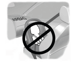
    Lincoln Aviator. Children and Airbags

    read more

     
    Copyright © 2026 www.liaviator2.com