
Lincoln Aviator: Evaporative Emissions - 3.0L EcoBoost / General Procedures - Evaporative Emission System Leak Test
Activation
Phase 1 - Leak Verification
-
Run the EVAP Test with the scan tool.
-
NOTE: Some small leaks may not be detected using the EVAP Test. If the system has passed the test but a leak is still suspected, then proceed to Phase 2.
If the EVAP system failed the EVAP Test, then proceed to Phase 2.
Phase 2 - System Leak Check
-
Disconnect the fuel vapor tube-to-EVAP canister purge valve quick connect coupling.
Refer to: Quick Release Coupling (310-00A Fuel System - General Information - 3.0L EcoBoost, General Procedures).
-
Connect the VACUTEC Smoke Machine Fuel EVAP Emissions System Tester to the fuel vapor tube quick connect coupling. Refer to the manufacturer's instructions.
-
NOTE: The battery ground cable was previously disconnected in the fuel vapor tube quick connect coupling procedure.
Connect the battery ground cable.
Refer to: Fuel Vapor Vent Valve (303-13A Evaporative Emissions - 3.0L EcoBoost, Removal and Installation).
-
Close the canister vent solenoid with the scan tool.
-
NOTE: The supplemental refueling adapter is located in the jack storage compartment.
Install the supplemental refueling adapter into the Easy FuelTM (capless) fuel tank filler pipe assembly.
-
NOTE: If smoke does not exit the fuel tank filler pipe neck area after the system is pressurized, open the canister vent solenoid with the scan tool to allow the air to purge. Once smoke is seen at the canister vent solenoid, close the canister vent solenoid with the scan tool.
Introduce smoke from the VACUTEC Smoke Machine Fuel EVAP Emissions System Tester into the EVAP system and verify that smoke is exiting the fuel tank filler pipe neck area. For additional information, refer to the manufacturer's instructions.
-
Remove the supplemental refueling adapter once smoke
is observed exiting the fuel tank filler pipe neck area.
-
Continue to enter smoke into the system for 60 seconds to obtain pressure.
-
Press and release the remote start button in
intervals of 15 seconds ON and 15 seconds OFF while checking for exiting
smoke.
-
Use the halogen light provided with the VACUTEC Smoke Machine Fuel EVAP Emissions System Tester to follow the EVAP system path and look for smoke exiting at the source of the leak(s).
-
Repair any leaks as necessary.
-
Repeat the leak test until the system passes.
 Diagnosis and Testing - Evaporative Emissions
Diagnostic Trouble Code (DTC) Chart
Diagnostics in this manual assume a certain skill level and knowledge of Ford-specific diagnostic practices.REFER to: Diagnostic Methods (100-00 General Information, Description and Operation)...
 Removal and Installation - Evaporative Emission Canister
Removal
WARNING:
Do not smoke, carry lighted tobacco or have an open flame of
any type when working on or near any fuel-related component...
Other information:
Lincoln Aviator 2020-2026 Service Manual: Removal and Installation - Battery Energy Control Module (BECM) - Plug-In Hybrid Electric Vehicle (PHEV)
Special Tool(s) / General Equipment Ford Diagnostic Equipment Removal WARNING: To prevent the risk of high-voltage shock, always follow precisely all warnings and service instructions, including instructions to depower the system...
Lincoln Aviator 2020-2026 Service Manual: General Procedures - Tire Pressure Monitoring System (TPMS) Sensor Activation
Special Tool(s) / General Equipment 204-D081A (204-D081) Tire Pressure Monitor (TPMS) Activation NOTE: The tire pressure sensors will go into a "sleep mode" when a vehicle is stationary to conserve battery power. The sensors do not transmit information while in sleep mode...
Categories
- Manuals Home
- Lincoln Aviator Owners Manual
- Lincoln Aviator Service Manual
- Wireless Accessory Charger (If Equipped)
- Child Safety Locks
- Opening and Closing the Hood
- New on site
- Most important about car
Remote Control
Passive Key
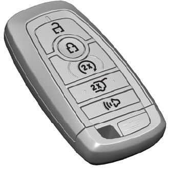
The passive key operates the power locks and the remote start system. The passive key must be in your vehicle to use the push button start.
Note: You may not be able to shift out of park (P) unless the passive key is inside your vehicle.
