
Lincoln Aviator 2020-2026 Service Manual / Chassis / Suspension / Wheels and Tires / General Procedures - Wheel to Hub Runout Minimization

Lincoln Aviator: Wheels and Tires / General Procedures - Wheel to Hub Runout Minimization

Check

NOTE: Wheel-to-hub optimization is important. Clearance between the wheel and hub can be used to offset or neutralize the Road Force® or run-out of the wheel and tire assembly. For every 0.001 inch of wheel-to-hub clearance, the Road Force® can be affected between 1 and 3 pounds depending on the tire stiffness.

  1. NOTE: The example below illustrates how the clearance between the wheel and the hub can be used to offset the high spot of radial run-out or Road Force®. Following the procedure will make sure of the best optimization.

    Position the wheel and tire assembly on the vehicle so that the high spot location of radial run-out or Road Force® is at the 6 o'clock position and install the wheel nuts by hand until snug.
  1. NOTE: Do not allow the full weight of the vehicle to rest on the tires while tightening the wheel nuts.

    Lower the vehicle until the tires make contact with the ground, slightly loading the suspension. Tighten the wheel nuts.
    Refer to: Wheel and Tire (204-04A Wheels and Tires, Removal and Installation).

    Diagnosis and Testing - Wheels and Tires

    Preliminary Inspection Verify the customer concern by carrying out a road test on a smooth road. If any vibrations are apparent, Refer to the Symptom Chart: NVH...

    General Procedures - Wheel to Tire Runout Minimization

    Check NOTE: Road Force® values in illustrations are shown in pounds. NOTE: Match mounting is a technique used to reduce radial runout or road force on wheel and tire assemblies...

    Other information:

    Lincoln Aviator 2020-2026 Service Manual: Description and Operation - Transmission Description


    Transmission Assembly Item Part Number Description 1 79027902 Torque converter 2 W714629W714629 Transmission fluid pan stud bolts (6 required) 3 W500215W500215 Transmission fluid pan bolts (12 required) 4 7A1947A194 Transmission fluid pan 5 7A1917A191 Transmission fluid pan gasket 6 7E3897E389 Transmission fluid level indicator and plug assembly 7 W708500W708500 Transmission fluid auxiliary pump tube bolt (model dependent) 8 7A2097A209 Transmission fluid auxiliary pump tube (model dependent) 9 W718548W718548 Transmission fluid auxiliary pump bolts (3 required) (model dependent) 10 7P0867P086 Transmission fluid auxiliary pump (model dependent) 11 7J1357J135 Transmission fluid auxiliary pump tube seal (model dependent) 12 W700123W700123 Transmission fluid filter bolt (71 mm length) 13 W500214W500214 Transmission fluid filter bolt (20 mm length) 14 7G1867G186 Transmission fluid filter 15 W708500W708500 Main control-to-transmission case bolts (68 mm length) (8 required) 16 7A1007A100 Main control assembly 17 7N2657N265 Main control-to-transmission fluid pump seal 18 7M1837M183 Intermediate Speed A (ISSA) sensor 19 7M1017M101 Turbine Shaft Speed (TSS) sensor 20 7H1037H103 Intermediate Speed B (ISSB) sensor 21 7H1037H103 Output Shaft Speed (OSS) sensor 22 W500213W500213 Transmission internal wiring harness bolts (2 required) 23 7G2767G276 Transmission internal wiring harness 24 W500215W500215 Transmission fluid pump bolts (4 required) 25 7A1037A103 Transmission fluid pump 26 7Z3027Z302 Transmission fluid pump seal 27 66586658 Transmission fluid pump driven gear outer cover 28 W718158W718158 Transmission fluid pump retaining ring 29 7A0807A080 Transmission fluid pump driven gear 30 W504755W504755 Transmission fluid pump driven gear inner cover bolts (2 required) 31 66586658 Transmission fluid pump driven gear inner cover 32 7K4407K440 Output shaft flange nut (RWD only) 33 7A0217A021 Output shaft flange (RWD only) 34 7N1357N135 Anti-ting washer (RWD only) 35 7G1007G100 Manual control shaft-to-Transmission Range (TR) sensor roll pin 36 W712713W712713-S442-S442 Park override lever nut 37 7J1677J167 Park override lever 38 7C4937C493 Manual control shaft 39 7H5577H557 Transmission Range (TR) sensor 40 7L2527L252 Park return spring 41 7D4107D410 Park pawl actuator rod 42 W716607W716607 Transmission Range (TR) sensor detent spring bolt 43 7E3327E332 Transmission Range (TR) sensor detent spring 44 7N1347N134 Front support assembly bolts (12 required) 45 7G0337G033 Front support assembly 46 7M1577M157-C-C B clutch (overdrive) snap ring 47 7C5767C576 B clutch (overdrive) pressure plate 48 7B4427B442-A-A B clutch (overdrive) steel plates (quantity model dependent) 49 7B1647B164 B clutch (overdrive) friction plates (quantity model dependent) 50 7J4027J402 B clutch (overdrive) separating springs (quantity model dependent) 51 7B4427B442-B-B B clutch (overdrive) apply plate 52 7G2067G206 One-Way Clutch (OWC) 53 7G4187G418 B clutch (overdrive) piston 54 7N1697N169 A clutch (intermediate) piston return spring snap ring 55 7G2977G297 A clutch (intermediate) piston return spring 56 7J0157J015 A clutch (intermediate) piston 57 7F2257F225 A clutch (intermediate) piston inner seal 58 7F2247F224 A clutch (intermediate) piston outer seal 59 7B0317B031 Front support-to-case seal 60 7M1577M157-J-J Torque converter hub seal snap ring 61 7A2487A248 Torque converter hub seal 62 W500204W500204 Front support cover and seal assembly bolt 63 7M1577M157 Front support cover and seal assembly snap ring 64 75707570 Front support cover and seal assembly 65 7F0737F073 Transmission fluid pump drive gear 66 66516651 Transmission fluid pump idler gear 67 7Z4267Z426 Transmission fluid pump idler gear bearing 68 7G0907G090 Stator support seal 69 — Clutch and planetary assembly 70 7P0807P080 A clutch (intermediate) wave spring 71 7A4067A406 A clutch (intermediate) apply plate (select fit) 72 7F2197F219 A clutch (intermediate) friction plates (quantity model dependent) 73 7F2207F220 A clutch (intermediate) steel plates (quantity model dependent) 74 7G1597G159 A clutch (intermediate) separating springs (quantity model dependent) 75 7B4377B437 A clutch (intermediate) pressure plate 76 7J3007J300 Selective shim 77 7H0327H032 Thrust bearing (T3) 78 7M1527M152-A-A Thrust bearing (T9) 79 7A0497A049 Output shaft and planetary carrier No...

    Lincoln Aviator 2020-2026 Service Manual: General Procedures - Refrigerant Oil Adding - Hybrid Electric Vehicle (HEV), Vehicles With: R134A Refrigerant


    Special Tool(s) / General Equipment Air Conditioning Service Unit Check NOTICE: Motorcraft® Electric A/C Compressor Oil (YN-32) only must be used as a refrigerant system lubricant for High Voltage Battery Electric vehicles. Addition of any oil other than Motorcraft® Electric A/C Compressor Oil (YN-32) to the High Voltage Battery Electric vehicle refrigerant system will damage the electric A/C compressor and contaminate the refrigerant system...

    Categories

    Activating Intelligent Access

    The intelligent access key must be within 3 ft (1 m) of the door or luggage compartment you intend to lock or unlock.

    At a Door

    Electronic door handles are on each door. Gently depress the switch inside the exterior door handle to unlock and open the door. An unlock symbol illuminates on the door window trim indicating your vehicle is unlocked.
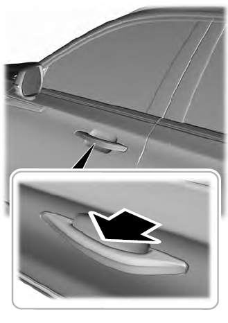
    Lincoln Aviator. Activating Intelligent Access

    read more

     
    Copyright © 2026 www.liaviator2.com