
Lincoln Aviator: Lighting / Interior Lighting
- Description and Operation - Interior Lighting - Overview
- Description and Operation - Interior Lighting - System Operation and Component Description
- Diagnosis and Testing - Interior Lighting
 Removal and Installation - Trailer Module (TRM)
Removal
NOTE:
Removal steps in this procedure may contain installation details.
NOTE:
This step is only necessary if the TRM is being replaced...
 Description and Operation - Interior Lighting - Overview
Overview
The interior lighting system consists of:
Courtesy lamps
Demand lamps
Ambient lighting
The
courtesy lamps provide illumination to the vehicle interior, front
scuff plates, exterior door handles, rear puddle lamps and below the
exterior mirrors when entering or exiting the vehicle or when requested
using the courtesy lamp switch located on the headlamp switch...
Other information:
Lincoln Aviator 2020-2026 Service Manual: Description and Operation - Body and Frame
The body consists of the following: Front bumper constructed of high-strength aluminum Rear bumper constructed of Boron and HSLA ultra high-strength steels Front frame rails constructed of high-strength aluminum Rear frame rails constructed of Boron ultra high-strength steel Fender reinforcement tube constructed of Dual Phase (DP) 800 high-strength steel Cast aluminum fender apron assembly Liftgate outer panel constructed of mild steel Body structure constructed of Boron, Dual Phase (DP) and high-strength steels Roof panel reinforcements constructed of Dual Phase (DP) 600 and mild steel Bolted, removable front fenders, hinged doors and hood Bodyside outer panels constructed of mild steel Steel hood hinges Mastic pads used on floor pan for sound deadening Front End Panel Margining NOTE: Margining specifications apply to left hand (LH) and right hand (RH) side of the vehicle unless stated...
Lincoln Aviator 2020-2026 Service Manual: Diagnosis and Testing - Parameter Identification (PID) Chart
Diagnostic PID Chart PID Acronym PID Name Description APP APP sensor APP APP1 APP sensor 1 APP 1 AST Time Since Start Time (in seconds) since the vehicle was started CLRDIST Distance since DTC cleared Distance driven since PCM DTCs were cleared ECT TCM ECT TCM Engine coolant temperature data provided to the TCM ENGLOAD Engine Load Engine load calculated by PCM ETC_ACT Electronic Throttle Control Actual Electronic Throttle Control Actual calculated by PCM FOOT_BRAKE Foot Brake - Foot brake state used by strategy Foot brake state used by strategy calculated by PCM GEAR_CMD Gear Commanded by Module PCM commanded transmission gear GEAR_ENGAGED Transmission Gear Engaged Transmission Gear Engaged GEAR_OSC# Gear Commanded by Output State Control Output state control commanded gear ISS_A_QF Transmission Input Shaft Speed Sensor -A- Quality Factor Transmission Input Shaft Speed Sensor -A- Quality Factor ISS_A_RAW Intermediate Speed -A- Raw Intermediate Speed -A- Raw ISS_B_RAW Intermediate Shaft Speed -B- Raw Intermediate Shaft Speed -B- Raw ISS_B_QF Transmission Input Shaft Speed Sensor -B- Quality Factor Transmission Input Shaft Speed Sensor -B- Quality Factor LINEDSD# Line Pressure Control Desired Commanded line pressure MIL_DIS The distance travelled since the (MIL) was activated The distance travelled since the MIL was activated OSS_QF Transmission Output Shaft Speed Sensor Quality Factor Fault status for the OSS sensor OSS_RAW Output Shaft Speed - Raw Actual speed of the OSS sensor (rpm) PCA Pressure Control Solenoid A LPC PCA AMP# Pressure Control Solenoid A LPC PCA_F Pressure Control Solenoid A Status LPC PWRT_FUNCMON_A Powertrain Secondary Monitor/Performance Fault A Powertrain Secondary Monitor/Performance Fault A PWRT_FUNCMON_B Powertrain Secondary Monitor/Performance Fault A Powertrain Secondary Monitor/Performance Fault A REALTIME Total time (ECU) has been active ECU Time running RPM_TCM Engine Revolutions Per Minute Engine rpm input to TCM SHFT_DROP Shift RPM Drop in Input Shaft Speed Below Expected Shift rpm drop in input shaft speed below expected SHFT_FLRE Shift RPM Rise in Input Shaft Speed Above Expected Shift rpm rise in input shaft speed above expected SHFT_ID Shift Identification of Shift (PID)s Lag, Time, Flare and Drop Shift identification of shift PIDs lag, time, flare and drop SHFT_LAG Shift Time Elapsed From 10% to 90% of Complete Actual time during shift between 10% and 90% complete SHFT_TIME Shift Time Elapsed From Commanded to 10% Complete Shift time 0% to 10% complete SNOWPLW_CFG Snowplow as configured in the (PCM)...
Categories
- Manuals Home
- Lincoln Aviator Owners Manual
- Lincoln Aviator Service Manual
- Drive Modes
- Anti-Theft Alarm
- Changing the Front Wiper Blades - Vehicles With: Heated Wiper Blades
- New on site
- Most important about car
Child Safety Locks
When the child safety locks are set, you cannot open the rear doors from the inside.
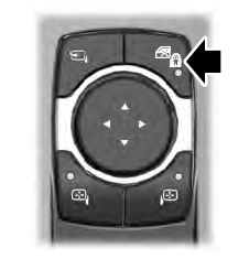
The child safety lock control is on the driver door.
Press the control to switch the child safety locks on. Press the control again to switch them off. A light on the child safety control illuminates when you switch them on.

Copyright © 2026 www.liaviator2.com