Lincoln Aviator 2020-2026 Service Manual / Electrical / Lighting / Exterior Lighting / Removal and Installation - Trailer Module (TRM)
Lincoln Aviator: Exterior Lighting / Removal and Installation - Trailer Module (TRM)
Removal
NOTE: Removal steps in this procedure may contain installation details.
-
NOTE: This step is only necessary if the TRM is being replaced.
Using a diagnostic scan tool, begin the PMI process for the TRM following the on-screen instructions.
Refer to: Module Configuration - System Operation and Component Description (418-01 Module Configuration, Description and Operation).
-
Remove the stoplamp switch.
Refer to: Stoplamp Switch (417-01 Exterior Lighting, Removal and Installation).
-
NOTE: Depending on vehicle options, you may need to remove the bracket bolt and lower the TRM to disconnect the electrical connectors.
Disconnect the TRM electrical connectors.
.jpg) |
-
Remove the TRM bracket bolt and the TRM.
Torque: 25 lb.in (2.8 Nm)
.jpg) |
Installation
-
To install, reverse the removal procedure.
-
NOTE: Carry out this step only if the TRM is being replaced.
Using a diagnostic scan tool, complete the PMI process for the TRM following the on-screen instructions.
Refer to: Module Configuration - System Operation and Component Description (418-01 Module Configuration, Description and Operation).
 Removal and Installation - Rear Lamp Fade Control Module
Removal
NOTE:
Removal steps in this procedure may contain installation details.
Remove the LH loadspace trim panel.
Refer to: Loadspace Trim Panel (501-05 Interior Trim and Ornamentation, Removal and Installation)...
Other information:
Lincoln Aviator 2020-2026 Service Manual: General Procedures - Parking Aid Camera Initialization
Using a scan tool select the controlling module for the parking aid camera(s). Carry out the LIN new module initialization. Follow the on-screen instructions. Check the vehicle for the active guidelines option...
Lincoln Aviator 2020-2026 Service Manual: Removal and Installation - Electric Brake Booster (EBB)
Removal NOTE: Removal steps in this procedure may contain installation details. NOTE: The EBB and the ABS module are serviced as an assembly and should not be separated. NOTE: The PMI process must begin with the current ABS module installed...
Categories
- Manuals Home
- Lincoln Aviator Owners Manual
- Lincoln Aviator Service Manual
- Resetting the System
- Body and Paint
- Tire Change Procedure
- New on site
- Most important about car
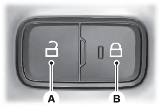
Locking and Unlocking the Doors from Inside

Locking the Doors
Press the lock switch on the door interior trim panel. The doors can no longer be released using the exterior door handle switches and the luggage compartment locks.
Copyright © 2026 www.liaviator2.com

