Lincoln Aviator: Interior Lighting / Description and Operation - Interior Lighting - Overview
Overview
The interior lighting system consists of:
- Courtesy lamps
- Demand lamps
- Ambient lighting
The courtesy lamps provide illumination to the vehicle interior, front scuff plates, exterior door handles, rear puddle lamps and below the exterior mirrors when entering or exiting the vehicle or when requested using the courtesy lamp switch located on the headlamp switch.
The courtesy lamps subsystem consists of:
- Interior overhead lamps
- Welcome mat lamps
- Rear puddle lamps
- Exterior door handle Light Emitting Diodes (LEDs)
- Front door illuminated scuff plates
- Cargo lamp
- Liftgate lamp
- Courtesy lamp switch (integrated into the overhead console)
- Door ajar switches (integrated into the door control modules)
- RGTM
- DDM
- PDM
- BCM
The demand lamps provide illumination to specific areas within the vehicle when needed.
The BCM supplies voltage to the demand lamps when the battery saver feature is not active.
The demand lamps subsystem consists of:
- Interior overhead lamps (map lamps)
- Vanity mirror lamps
- Glove compartment lamp
- Media bin lamps
- Storage bin lamps
- BCM
The ambient lighting subsystem consists of:
- Ambient lighting LEDs
- FDIM (touchscreen)
- BCM
The ambient lighting is controlled using the FDIM (touchscreen) controls. The ambient lighting provides aesthetically colored illumination to the following locations for illuminated entry or when the ignition is in RUN with the parking lamps on:
- Instrument panel lamps
- Front and rear floor console cup holders
- Center console pass thru
- Front and rear doors
- Front footwells
- Rear footwells
 Description and Operation - Interior Lighting - System Operation and Component Description
System Operation
System Diagram
Item
Description
1
Rear footwell ambient lighting LEDs
2
LIN
3
DDM
4
LH welcome mat lamp
5
RH welcome mat lamp
6
PDM
7
Front cup holder lighting LEDs
8
Front footwell ambient lighting LEDs
9
Rear door ambient lighting LEDs
10
HS-CAN1
11
APIM
12
HS-CAN3
13
FDIM
14
GWM
15
MS-CAN
16
Liftgate lamp
17
Vanity mirror lamps
18
Glove compartment lamp
19
Console/bin lamps
20
LH second row interior lamp
21
RH second row interior lamp
22
Cargo lamp
23
Third row interior lamp
24
LIN
25
Overhead console
26
RGTM
27
LIN
28
Headlamp switch
29
Scuff plate lamps
30
Second row cup holder lighting LEDs
31
Front door ambient lighting LEDs
32
Instrument panel ambient lamps
33
Center console pass thru ambient lamp
34
Door latch control modules
35
Door ajar switch
36
Rear door puddle lamps
37
LIN
38
BCM
39
Exterior door handle LEDs
Network Message Chart
DDM And PDM Network Input Messages
Broadcast Message
Originating Module
Message Purpose
Welcome mat lamp activation
GWM
Provides welcome mat lamp request from the GWM to activate the exterior mirror welcome mat lamps...
Other information:
Lincoln Aviator 2020-2026 Service Manual: Removal and Installation - Exterior Rear Door Handle
Removal NOTE: LH (left-hand) side shown, RH (right-hand) side similar. NOTE: Removal steps in this procedure may contain installation details. Remove the rear door window regulator and motor. Refer to: Rear Door Window Regulator and Motor (501-11 Glass, Frames and Mechanisms, Removal and Installation)...
Lincoln Aviator 2020-2026 Service Manual: General Procedures - Brake Disc Machining
Repair NOTE: On-Vehicle Brake Lathe Training Videos Vehicle preparation. Click here to view a video version of this procedure. Mounting the machine. Click here to view a video version of this procedure...
Categories
- Manuals Home
- Lincoln Aviator Owners Manual
- Lincoln Aviator Service Manual
- Tire Change Procedure
- Keyless Entry
- Description and Operation - Body and Frame
- New on site
- Most important about car
Remote Control
Passive Key

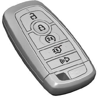
The passive key operates the power locks and the remote start system. The passive key must be in your vehicle to use the push button start.
Note: You may not be able to shift out of park (P) unless the passive key is inside your vehicle.

