
Lincoln Aviator: Capacities and Specifications - Excluding: Plug-In Hybrid Electric Vehicle (PHEV) / Rear Axle
Capacities

Materials

 Front Axle
C..
 Washer Reservoir
C..
Other information:
Lincoln Aviator 2020-2026 Service Manual: Diagnosis and Testing - Body Control Module C (BCMC)
Diagnostic Trouble Code (DTC) Chart Diagnostics in this manual assume a certain skill level and knowledge of Ford-specific diagnostic practices. REFER to: Diagnostic Methods (100-00 General Information, Description and Operation). Diagnostic Trouble Code Chart Module DTC Description Action BCMC U0100:87 Lost Communication With ECM/PCM "A": Missing Message GO to Pinpoint Test A BCMC U0111:87 Lost Communication With Battery Energy Control Module "A": Missing Message GO to Pinpoint Test B BCMC U0140:87 Lost Communication With Body Control Module: Missing Message GO to Pinpoint Test C BCMC U0164:87 Lost Communication With HVAC Control Module: Missing Message GO to Pinpoint Test D BCMC U024D:87 Lost Communication With "Seat Control Module J": Missing Message GO to Pinpoint Test E BCMC U0293:87 Lost Communication With Hybrid/EV Powertrain Control Module: Missing Message GO to Pinpoint Test F BCMC U1000:00 Solid State Driver Protection Active: Driver Disabled: No Sub Type Information GO to Pinpoint Test G BCMC U2100:00 Initial Configuration Not Complete: No Sub Type Information GO to Pinpoint Test H BCMC U2200:00 Control Module Configuration Memory Corrupt: No Sub Type Information GO to Pinpoint Test H BCMC U3000:49 Control Module: Internal Electronic Failure GO to Pinpoint Test I BCMC U3003:16 Battery Voltage: Circuit Voltage Below Threshold GO to Pinpoint Test J BCMC U3003:17 Battery Voltage: Circuit Voltage Above Threshold GO to Pinpoint Test K Pinpoint Tests PINPOINT TEST A : U0100:87 Refer to Wiring Diagrams Cell 14 for schematic and connector information...
Lincoln Aviator 2020-2026 Owners Manual: Changing the Rear Wiper Blades
You can improve poor wiper quality by cleaning the wiper blades and the windshield. Replace the wiper blades at least annually for optimum performance. Switch your vehicle ignition on and off to move the wiper arm to the service position. Lift the wiper arm and then press the wiper blade locking buttons together...
Categories
- Manuals Home
- Lincoln Aviator Owners Manual
- Lincoln Aviator Service Manual
- Opening and Closing the Hood
- Fuel Quality
- Configuring The Head Up Display
- New on site
- Most important about car
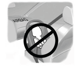
Children and Airbags
WARNING: Airbags can kill or injure a child in a child restraint. Never place a rear-facing child restraint in front of an active airbag. If you must use a forward-facing child restraint in the front seat, move the seat upon which the child restraint is installed all the way back.

Copyright © 2026 www.liaviator2.com