Lincoln Aviator 2020-2026 Service Manual / Electrical / Electronic Feature Group / Remote Convenience
Lincoln Aviator: Electronic Feature Group / Remote Convenience
- Description and Operation - Universal Transmitter - System Operation and Component Description
- Diagnosis and Testing - Universal Transmitter
 Removal and Installation - Remote Function Actuator (RFA) Module
Removal
NOTE:
This step is only necessary when installing a new component.
NOTE:
If installing a new module, it is necessary to
upload the module configuration information to the diagnostic scan tool
prior to removing the module...
 Description and Operation - Universal Transmitter - System Operation and Component Description
System Operation
Universal Transmitter
The universal transmitter learns a hand-held transmitter radio
frequency code and stores the code in memory...
Other information:
Lincoln Aviator 2020-2026 Service Manual: General Procedures - Air Conditioning (A/C) System Recovery, Evacuation and Charging - Vehicles With: R1234YF Refrigerant
Special Tool(s) / General Equipment Air Conditioning Service Unit Refrigerant Identification Equipment Recovery NOTICE: Use an A/C refrigerant analyzer before recovering any of the vehicle's A/C refrigerant. Failure to do so puts the shop's bulk refrigerant at risk of contamination...
Lincoln Aviator 2020-2026 Service Manual: Description and Operation - Frame Assembly - Overview
Overview The front subframe is bolted to the body and is used to: aid in structural support. provide mounting surfaces for the steering gear. provide mounting surfaces for the front suspension lower control arms, the engine mounts and for the front stabilizer bar...
Categories
- Manuals Home
- Lincoln Aviator Owners Manual
- Lincoln Aviator Service Manual
- Changing the Front Wiper Blades - Vehicles With: Heated Wiper Blades
- Body and Paint
- Tire Change Procedure
- New on site
- Most important about car
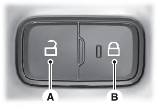
Locking and Unlocking the Doors from Inside

Locking the Doors
Press the lock switch on the door interior trim panel. The doors can no longer be released using the exterior door handle switches and the luggage compartment locks.
Copyright © 2026 www.liaviator2.com
