Lincoln Aviator: High Voltage Battery, Mounting and Cables / Removal and Installation - Battery Energy Control Module (BECM) - Plug-In Hybrid Electric Vehicle (PHEV)
Special Tool(s) / General Equipment
| Ford Diagnostic Equipment |
Removal
.jpg) WARNING:
To prevent the risk of high-voltage shock, always follow
precisely all warnings and service instructions, including instructions
to depower the system. The high-voltage system utilizes approximately
450 volts DC, provided through high-voltage cables to its components and
modules. The high-voltage cables and wiring are identified by orange
harness tape or orange wire covering. All high-voltage components are
marked with high-voltage warning labels with a high-voltage symbol.
Failure to follow these instructions may result in serious personal
injury or death.
WARNING:
To prevent the risk of high-voltage shock, always follow
precisely all warnings and service instructions, including instructions
to depower the system. The high-voltage system utilizes approximately
450 volts DC, provided through high-voltage cables to its components and
modules. The high-voltage cables and wiring are identified by orange
harness tape or orange wire covering. All high-voltage components are
marked with high-voltage warning labels with a high-voltage symbol.
Failure to follow these instructions may result in serious personal
injury or death.
NOTICE: BECM should be carefully handled, if dropped must be scrapped.
-
Refer to: Health and Safety Precautions (100-00 General Information, Description and Operation)..jpg) WARNING:
Before beginning any service procedure in this
section, refer to Safety Warnings in section 100-00 General Information.
Failure to follow this instruction may result in serious personal
injury.
WARNING:
Before beginning any service procedure in this
section, refer to Safety Warnings in section 100-00 General Information.
Failure to follow this instruction may result in serious personal
injury.
-
NOTE: This step is only necessary when installing a new component.
NOTE: Use the previous FDRS vehicle session or start a session manually by entering the VIN.
Download the BECM information to the diagnostic tool using the Programmable Modules Installation routine.
Refer to: Module Programming (418-01 Module Configuration, General Procedures).
Use the General Equipment: Ford Diagnostic Equipment
-
Remove the high voltage battery.
Refer to: High Voltage Battery - Plug-In Hybrid Electric Vehicle (PHEV) (414-03A High Voltage Battery, Mounting and Cables, Removal and Installation).
-
Remove the fasteners and the high voltage battery cover.
.jpg) |
-
Disconnect the electrical connectors, detach the retainers and position the wire harness aside.
.jpg) |
-
NOTICE: Wait for 10 seconds after disconnecting the first electrical connector or component damage will occur.
NOTICE: The following steps must be performed in the sequence show or component damage will occur.
-
Disconnect the electrical connector and wait 10 seconds.
-
Disconnect the electrical connectors in the sequence shown.
-
Disconnect the electrical connector and wait 10 seconds.
.jpg) |
-
Remove the nuts and the BECM.
.jpg) |
Installation
-
Install the BECM and the nuts.
Torque: 106 lb.in (12 Nm)
.jpg) |
-
NOTICE: The following step must be performed in the sequence show or component damage will occur.
Connect the electrical connectors in the sequence shown.
 Attach the retainers and connect the wire harness electrical connector.
.jpg) |
-
NOTE: Make sure the correct position of seal, replace with new seal if necessary.
.jpg) |
-
The fasteners must be installed by hand before final tightening.
Tighten the fasteners in sequence shown in 2 stages.
Torque:
Stage 1: 53 lb.in (6 Nm)
Stage 2: 80 lb.in (9 Nm)
.jpg) |
-
Check the high voltage battery pack for leaks.
Refer to: High Voltage Battery Leak Test - Plug-In Hybrid Electric Vehicle (PHEV) (414-03A High Voltage Battery, Mounting and Cables, General Procedures).
-
Install the high voltage battery.
Refer to: High Voltage Battery - Plug-In Hybrid Electric Vehicle (PHEV) (414-03A High Voltage Battery, Mounting and Cables, Removal and Installation).
-
NOTE: This step is only necessary when installing a new component.
Upload the BECM information from the diagnostic tool using the Programmable Modules Installation routine.
Refer to: Module Programming (418-01 Module Configuration, General Procedures).
 General Procedures - High Voltage System De-energizing
Depower
WARNING:
To prevent the risk of high-voltage shock, always follow
precisely all warnings and service instructions, including instructions
to depower the system...
 Removal and Installation - High Voltage Battery - Plug-In Hybrid Electric Vehicle (PHEV)
Special Tool(s) /
General Equipment
Ford Diagnostic Equipment
Hose Clamp(s)
Powertrain Jack
Removal
WARNING:
To prevent the risk of high-voltage shock, always follow
precisely all warnings and service instructions, including instructions
to depower the system...
Other information:
Lincoln Aviator 2020-2025 Service Manual: Removal and Installation - Rear Driveshaft
Special Tool(s) / General Equipment 100-001 (T50T-100-A) Slide Hammer 205-832Remover, HalfshaftTKIT-2006C-FFMFLMTKIT-2006C-LMTKIT-2006C-ROW Slide Hammer Materials Name Specification Motorcraft® Premium Long-Life GreaseXG-1-E1 ESA-M1C75-B Removal NOTE: The maximum articulation of the flex coupling is 4 degrees...
Lincoln Aviator 2020-2025 Service Manual: Removal and Installation - Steering Column Multifunction Switch LH
Removal NOTE: Removal steps in this procedure may contain installation details. Remove the steering column shrouds. Refer to: Steering Column Shrouds (501-05 Interior Trim and Ornamentation, Removal and Installation). If equipped, remove the steering column control switch...
Categories
- Manuals Home
- Lincoln Aviator Owners Manual
- Lincoln Aviator Service Manual
- Refueling
- Resetting the System
- Keyless Entry
- New on site
- Most important about car
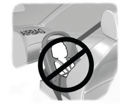
Children and Airbags
WARNING: Airbags can kill or injure a child in a child restraint. Never place a rear-facing child restraint in front of an active airbag. If you must use a forward-facing child restraint in the front seat, move the seat upon which the child restraint is installed all the way back.

