Lincoln Aviator: Hydraulic Brake Actuation / Removal and Installation - Brake Pedal and Bracket
Removal
NOTE: Removal steps in this procedure may contain installation details.
-
Remove the BCM.
Refer to: Body Control Module (BCM) (419-10 Multifunction Electronic Modules, Removal and Installation).
-
NOTICE: Do not service the brake pedal or brake booster without first removing the stoplamp switch. The switch must be removed with the brake pedal in the at-rest position. The switch plunger must be compressed for the switch to rotate in the bracket. Attempting to remove the switch when the plunger is extended (during pedal apply) will result in damage to the switch.
Remove the stoplamp switch.
Refer to: Stoplamp Switch (417-01 Exterior Lighting, Removal and Installation).
-
Push inward on the tabs and remove the clevis pin. Discard the clevis pin.
.jpg) |
-
Remove the brake pedal and bracket assembly mounting nuts and bolts. Discard the nuts and bolts.
.jpg) |
Installation
-
NOTICE: Do not press, pull or otherwise move the brake pedal while installing the stoplamp switch. The switch must be installed with the booster push rod attached to the brake pedal and with the brake pedal in the at-rest position. Installing the switch with the brake pedal in any other position will result in incorrect adjustment and may damage the switch.
To install, reverse the removal procedure.
-
Install the brake pedal and bracket assembly and tighten the new nuts and bolts in the sequence shown.
Torque: 177 lb.in (20 Nm)
.jpg) |
 Removal and Installation - Brake Fluid Reservoir
Removal
NOTICE:
Siphon the brake fluid from the HCU/EBB reservoir, if the
reservoir is not emptied there will be a large amount of brake fluid
spilled in the engine compartment...
 Removal and Installation - Remote Brake Fluid Reservoir
Removal
NOTICE:
Siphon the brake fluid from the HCU/EBB reservoir, if the
reservoir is not emptied there will be a large amount of brake fluid
spilled in the engine compartment...
Other information:
Lincoln Aviator 2020-2026 Service Manual: Description and Operation - Engine - Overview
Overview The 3.0L Gasoline Turbocharged Direct Injection (GTDI) (4V) is a V-6 engine with the following features: Interference design engine Dual overhead camshafts Four valves per cylinder Gasoline Turbocharged Direct Injection (GTDI) Composite intake manifold Aluminum cylinder heads Compacted graphite iron cylinder block Twin independent variable cam timing (Ti-VCT) An electronic ignition system with 6 ignition coils Continuous variable displacement oil pump Engine Identification For quick identification, refer to the safety certification decal...
Lincoln Aviator 2020-2026 Service Manual: Removal and Installation - Spark Plugs
Removal Remove the ignition coil-on-plugs. Refer to: Ignition Coil-On-Plug (303-07A Engine Ignition - 3.0L EcoBoost, Removal and Installation). Use compressed air to remove any foreign material in the spark plug well before removing the spark plugs...
Categories
- Manuals Home
- Lincoln Aviator Owners Manual
- Lincoln Aviator Service Manual
- Garage Door Opener
- Fuel Quality
- Configuring The Head Up Display
- New on site
- Most important about car
Children and Airbags
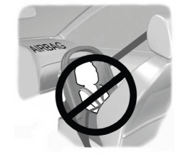
WARNING: Airbags can kill or injure a child in a child restraint. Never place a rear-facing child restraint in front of an active airbag. If you must use a forward-facing child restraint in the front seat, move the seat upon which the child restraint is installed all the way back.

