Lincoln Aviator 2020-2026 Service Manual / Powertrain / Engine / Engine Cooling - 3.0L EcoBoost / Removal and Installation - Coolant Pump
Lincoln Aviator: Engine Cooling - 3.0L EcoBoost / Removal and Installation - Coolant Pump
Special Tool(s) / General Equipment
| Hose Clamp Remover/Installer |
Removal
-
Drain the cooling system.
Refer to: Engine Cooling System Draining, Vacuum Filling and Bleeding (303-03A Engine Cooling - 3.0L EcoBoost, General Procedures).
-
Remove the air cleaner.
Refer to: Air Cleaner (303-12 Intake Air Distribution and Filtering - 3.0L EcoBoost/3.0L EcoBoost – Hybrid (BQ), Removal and Installation).
-
Remove the CAC outlet pipe.
Refer to: Charge Air Cooler (CAC) Outlet Pipe (303-12 Intake Air Distribution and Filtering - 3.0L EcoBoost/3.0L EcoBoost – Hybrid (BQ), Removal and Installation).
-
Loosen the coolant pump pulley bolts.
.jpg) |
-
Remove the accessory drive belt.
Refer to: Accessory Drive Belt (303-05A Accessory Drive - 3.0L EcoBoost, Removal and Installation).
NOTE: Completely remove the accessory drive belt to prevent coolant contamination.
-
Remove the bolts and the coolant pump pulley.
.jpg) |
-
Remove the thermostat.
Refer to: Thermostat (303-03A Engine Cooling - 3.0L EcoBoost, Removal and Installation).
-
Remove the bolt and the idler pulley.
.jpg) |
-
-
Release the clamp and disconnect the coolant hose.
Use the General Equipment: Hose Clamp Remover/Installer
-
Disconnect the coolant hose quick release coupling.
-
Release the clamp and disconnect the coolant hose.
.jpg) |
-
NOTE: Use caution to prevent damaging the coolant inlet pipe grommet.
Remove the bolts and the coolant pump.
.jpg) |
-
Remove and discard the coolant pump gasket and seal.
.jpg) |
Installation
-
-
Lubricate the inside and the outside diameter of the grommet with clean engine coolant.
Refer to: Specifications (303-03A Engine Cooling - 3.0L EcoBoost, Specifications).
-
Install the grommet so it is flush with the leading
edge of the coolant pump housing to aid in alignment during assembly.
-
Lubricate the inside and the outside diameter of the grommet with clean engine coolant.
.jpg) |
-
NOTE: Verify the front cover dowel pins are aligned to the coolant pump and that the coolant pump is fully seated prior to installing the fasteners.
-
Using a new gasket, install the coolant pump and the bolts.
Torque:
Fasteners 1-7:
Stage 1: 89 lb.in (10 Nm)
Stage 2: 45°
-
Torque:
Fastener 8: 18 lb.ft (24 Nm)
-
Using a new gasket, install the coolant pump and the bolts.
.jpg) |
-
-
Connect the coolant hose and position the clamp.
Use the General Equipment: Hose Clamp Remover/Installer
-
Connect the coolant hose quick release coupling.
-
Connect the coolant hose and position the clamp.
.jpg) |
-
Install the idler pulley and the bolt.
Torque: 35 lb.ft (47.5 Nm)
.jpg) |
-
Install the thermostat.
Refer to: Thermostat (303-03A Engine Cooling - 3.0L EcoBoost, Removal and Installation).
-
Position the coolant pump pulley and install the fasteners finger tight.
.jpg) |
-
Install the accessory drive belt.
Refer to: Accessory Drive Belt (303-05A Accessory Drive - 3.0L EcoBoost, Removal and Installation).
-
Tighten the coolant pump pulley fasteners.
Torque: 18 lb.ft (24 Nm)
.jpg) |
-
Install the CAC outlet pipe.
Refer to: Charge Air Cooler (CAC) Outlet Pipe (303-12 Intake Air Distribution and Filtering - 3.0L EcoBoost/3.0L EcoBoost – Hybrid (BQ), Removal and Installation).
-
Install the air cleaner.
Refer to: Air Cleaner (303-12 Intake Air Distribution and Filtering - 3.0L EcoBoost/3.0L EcoBoost – Hybrid (BQ), Removal and Installation).
-
Fill and bleed the cooling system.
Refer to: Engine Cooling System Draining, Vacuum Filling and Bleeding (303-03A Engine Cooling - 3.0L EcoBoost, General Procedures).
 Removal and Installation - Coolant Outlet Connector
Special Tool(s) /
General Equipment
Hose Clamp Remover/Installer
Removal
Remove the direct injection fuel rail LH.
Refer to: Direct Injection Fuel Rail LH (303-04A Fuel Charging and Controls - 3...
 Removal and Installation - Cooling Fan Motor and Shroud
Special Tool(s) /
General Equipment
Hose Clamp Remover/Installer
Removal
Remove the air cleaner.
Refer to: Air Cleaner (303-12 Intake Air Distribution and Filtering - 3...
Other information:
Lincoln Aviator 2020-2026 Service Manual: Removal and Installation - Cabin Air Filter
Removal Fully lower the glove compartment. Remove the check strap. Push the stop tabs inward. Remove the screws and lower the cabin air filter door. Remove the cabin air filter...
Lincoln Aviator 2020-2026 Service Manual: Removal and Installation - Auxiliary Power Point
Special Tool(s) / General Equipment 501-194Remover, Power PointTKIT-2014D-ROW2TKIT-2014D-FL_ROW Removal Open the power point cover. Position the power point extractor so that it engages in the adjacent slots in the power point socket...
Categories
- Manuals Home
- Lincoln Aviator Owners Manual
- Lincoln Aviator Service Manual
- Description and Operation - Jacking and Lifting
- Body and Paint
- Anti-Theft Alarm
- New on site
- Most important about car
Activating Intelligent Access
The intelligent access key must be within 3 ft (1 m) of the door or luggage compartment you intend to lock or unlock.
At a Door
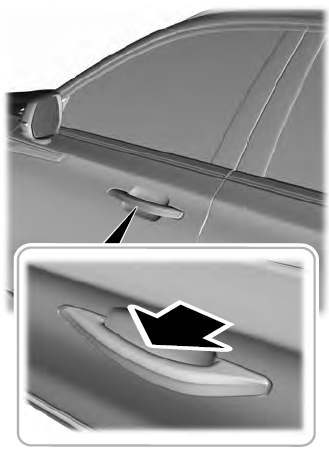
Electronic door handles are on each door. Gently depress the switch inside the exterior door handle to unlock and open the door. An unlock symbol illuminates on the door window trim indicating your vehicle is unlocked.

Copyright © 2026 www.liaviator2.com
