Lincoln Aviator 2020-2026 Service Manual / Powertrain / Engine / Engine Cooling - 3.0L EcoBoost / Removal and Installation - Cooling Fan Motor and Shroud
Lincoln Aviator: Engine Cooling - 3.0L EcoBoost / Removal and Installation - Cooling Fan Motor and Shroud
Special Tool(s) / General Equipment
| Hose Clamp Remover/Installer |
Removal
-
Remove the air cleaner.
Refer to: Air Cleaner (303-12 Intake Air Distribution and Filtering - 3.0L EcoBoost/3.0L EcoBoost – Hybrid (BQ), Removal and Installation).
-
-
Detach the coolant hose retainers.
-
Release the clamps and disconnect the coolant hoses.
Use the General Equipment: Hose Clamp Remover/Installer
-
Remove the bolt and position the degas bottle aside.
Torque: 44 lb.in (5 Nm)
-
Detach the coolant hose retainers.
.jpg) |
-
Disconnect the electrical connector and detach the wiring harness retainers.
.jpg) |
-
Remove the bolt and position the CAC hose aside.
Torque: 93 lb.in (10.5 Nm)
.jpg) |
-
Release the clips and position the radiator air deflector aside.
.jpg) |
-
NOTE: Raise the cooling fan motor and shroud from the RH (Right-Hand) side.
Remove the bolts and the cooling fan motor and shroud.
Torque: 71 lb.in (8 Nm)
.jpg) |
-
Remove the bolts and the CAC hose support bracket.
Torque: 49 lb.in (5.5 Nm)
.jpg) |
Installation
-
To install, reverse the removal procedure.
 Removal and Installation - Coolant Pump
Special Tool(s) /
General Equipment
Hose Clamp Remover/Installer
Removal
Drain the cooling system.
Refer to: Engine Cooling System Draining, Vacuum Filling and Bleeding (303-03A Engine Cooling - 3...
 Removal and Installation - Cooling Module
Removal
NOTE:
Removal steps in this procedure may contain installation details.
With the vehicle in NEUTRAL, position it on a hoist.
Refer to: Jacking and Lifting (100-02 Jacking and Lifting, Description and Operation)...
Other information:
Lincoln Aviator 2020-2026 Owners Manual: Hands-Free Feature (If Equipped)
Make sure you have the passive key within 3 ft (1 m) of the liftgate. Stand behind your vehicle, and face the liftgate. Move your foot, in a single-kick motion, without pausing, under and away from the rear bumper detection area. The liftgate opens or closes...
Lincoln Aviator 2020-2026 Service Manual: Removal and Installation - Roof Opening Panel Shield
Removal NOTE: Removal steps in this procedure may contain installation details. Remove the roof opening panel frame. Refer to: Roof Opening Panel Frame (501-17 Roof Opening Panel, Removal and Installation). Remove the front cross bar from the couplers on both sides...
Categories
- Manuals Home
- Lincoln Aviator Owners Manual
- Lincoln Aviator Service Manual
- Resetting the System
- Fuel Quality
- Garage Door Opener
- New on site
- Most important about car
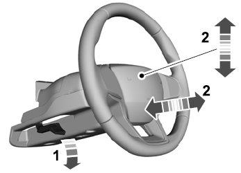
Adjusting the Steering Wheel - Vehicles With: Manual Adjustable Steering Column
WARNING: Do not adjust the steering wheel when your vehicle is moving.
Note: Make sure that you are sitting in the correct position.
Unlock the steering column. Adjust the steering wheel to the desired position.
Copyright © 2026 www.liaviator2.com
