Lincoln Aviator: Driveshaft / Removal and Installation - Front Driveshaft
Special Tool(s) / General Equipment
| Strap Wrench | |
| Transmission Jack |
Materials
| Name | Specification |
|---|---|
| Motorcraft® High Temperature 4x4 Front Axle and Wheel Bearing Grease XG-11 |
WSS-M1C267-A1 |
| Slip Yoke Grease 5L3Z-19A506-A |
- |
Removal
All vehicles
-
Disconnect battery terminals.
Refer to: Battery Disconnect and Connect (414-01 Battery, Mounting and Cables, General Procedures).
-
Drain the transfer case Fluid.
Refer to: Transmission Fluid Cooler - Backflushing and Cleaning (307-02B Transmission Cooling - 10-Speed Automatic Transmission – 10R80 MHT, General Procedures).
-
Remove Catalytic Converter RH.
Refer to: Catalytic Converter RH - Plug-In Hybrid Electric Vehicle (PHEV) (309-00B Exhaust System - 3.0L EcoBoost – Hybrid (BQ), Removal and Installation).
Refer to: Catalytic Converter RH - Plug-In Hybrid Electric Vehicle (PHEV) (309-00B Exhaust System - 3.0L EcoBoost – Hybrid (BQ), Removal and Installation).
-
Remove the nut, bolts and the front exhaust heat shield.
.jpg) |
3.0L EcoBoost - Hybrid
-
Remove the transmission fluid cooler.
Refer to: Transmission Fluid Cooler (307-02B Transmission Cooling - 10-Speed Automatic Transmission – 10R80 MHT, Removal and Installation).
All vehicles
-
NOTICE: The driveshaft yoke fits tightly on the front axle pinion stem with circlip. Never hammer on the driveshaft or any of its components to disengage the driveshaft yoke from front axle pinion stem. Pry only in the area shown with a suitable tool, to disengage the driveshaft yoke from the front axle pinion stem or damage to the driveshaft yoke and pinion stem can occur.
NOTE: Care should be taken not to damage the driveshaft splines.
Use pry tool to disengage circlip that holds the front driveshaft plug-on yoke to the front axle pinion stem.
.jpg) |
-
Remove the bolts and the transfer case heat shield.
 |
-
NOTE: Take extra care not to damage the component.
Position aside and support the rear driveshaft.
-
Mark the driveshaft flex coupling to the transfer case flange.
-
Remove and discard the driveshaft flex coupling to transfer case flange bolts.
-
Mark the driveshaft flex coupling to the transfer case flange.
.jpg) |
-
NOTICE: Secure the transmission to the transmission jack with a safety strap.
NOTICE: Make sure the transmission jack makes contact on the outer ribs of the transmission fluid pan.
Using a high-lift transmission jack, support the transmission.
Use the General Equipment: Transmission Jack
Use the General Equipment: Strap Wrench
.jpg) |
-
Detach the transfer case vent hose and position aside.
.jpg) |
-
Disconnect the transfer case motor assembly electrical connector and position the wiring harness aside.
.jpg) |
-
Remove the transmission support crossmember.
-
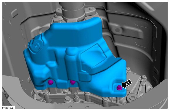
Remove the transfer case to transmission bell housing bolts.
.jpg) |
-
Remove the transfer case to transmission bell housing bolts.
.jpg) |
-
NOTE: This step requires the aid of another technician.
Disconnect the transfer case from transmission and position aside.
.jpg) |
-
Remove the front driveshaft from vehicle.
.jpg) |
-
Remove and discard the front driveshaft slip yoke boot and clamp.
Refer to: Front Driveshaft Slip Yoke Boot (205-01 Driveshaft, Removal and Installation).
-
Remove and discard the front axle pinion stem circlip.
.jpg) |
-
Remove and discard the front axle pinion stem O-ring.
.jpg) |
Installation
All vehicles
-
NOTE: Make sure that the mating faces are clean and free of foreign material.
Clean the debris or contamination of the splines, circlip groove and the surface near the O-ring groove.
.jpg) |
-
NOTE: Make sure that a new component is installed.
NOTE: Make sure that the O-ring is seated correctly.
Install a new front axle pinion stem O-ring.
.jpg) |
-
NOTICE: The circlip must be side-loaded on to the front axle pinion stem to prevent deformation of the circlip.
NOTE: Make sure that a new component is installed.
NOTE: Make sure that the circlip is seated correctly.
Install the new front axle pinion stem circlip.
.jpg) |
-
NOTICE: Do not over-lubricate the driveshaft components. Using excessive grease may damage the driveshaft components.
Lubricate the front driveshaft plug-on yoke splines with grease.
Material: Slip Yoke Grease / 5L3Z-19A506-A
.jpg) |
-
Install the front driveshaft slip yoke boot.
Refer to: Front Driveshaft Slip Yoke Boot (205-01 Driveshaft, Removal and Installation).
-
Install the front driveshaft to the front axle pinion stem.
.jpg) |
-
NOTICE: Do not over-lubricate the driveshaft components. Using excessive grease may damage the driveshaft components.
Lubricate the transfer case inner splines with grease.
Material: Motorcraft® High Temperature 4x4 Front Axle and Wheel Bearing Grease / XG-11 (WSS-M1C267-A1)
.jpg) |
-
NOTE: This step requires the aid of another technician.
Connect the transfer case to the transmission bell housing.
.jpg) |
-
Install the transfer case to transmission bell housing bolts.
Torque: 168 lb.in (19 Nm)
|
-
Install the transfer case to transmission bell housing bolts.
Torque: 168 lb.in (19 Nm)
|
-
Install the transmission support crossmember.
-
Connect transfer case motor assembly electrical connector and position the wiring harness properly.
|
-
Attach the transfer case vent hose.
|
-
Unstrap and lower the transmission jack.
Use the General Equipment: Transmission Jack
|
-
-
Ensure the electrical wiring harness is properly
routed near U-joint and not contacting to driveshaft at any point.
-
Ensure the driveshaft boot is seated to the transfer case slinger.
-
Ensure the electrical wiring harness is properly
routed near U-joint and not contacting to driveshaft at any point.
.jpg) |
-
NOTICE: Do not over articulate the driveshaft or damage may occur.
NOTE: Do not force the flex coupling bushing on the transfer case output shaft or damage will occur.
-
Align the index-mark on driveshaft flex coupling to the transfer case flange.
-
Install the new driveshaft flex coupling to transfer case flange bolts.
Torque: 81 lb.ft (110 Nm)
-
Align the index-mark on driveshaft flex coupling to the transfer case flange.
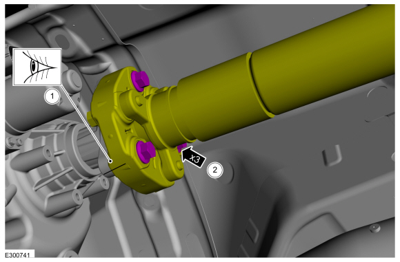 |
-
NOTICE: Ensure that the transfer case heatshield does not contact the driveshaft flex coupling.
Install the transfer case heat shield and the bolts.
Torque: 21 lb.ft (28 Nm)
|
All vehicles
-
NOTE: Maintain the suitable possible distance between components.
Ensure the distance between the edge of plug-on yoke and the front axle pinion nut.
.jpg) |
-
Install the front exhaust heat shield and the nut, bolts.
Torque: 89 lb.in (10 Nm)
|
-
Install Catalytic Converter RH.
Refer to: Catalytic Converter RH - Plug-In Hybrid Electric Vehicle (PHEV) (309-00B Exhaust System - 3.0L EcoBoost – Hybrid (BQ), Removal and Installation).
Refer to: Catalytic Converter RH - Plug-In Hybrid Electric Vehicle (PHEV) (309-00B Exhaust System - 3.0L EcoBoost – Hybrid (BQ), Removal and Installation).
3.0L EcoBoost - Hybrid
-
Install the transmission fluid cooler.
Refer to: Transmission Fluid Cooler (307-02B Transmission Cooling - 10-Speed Automatic Transmission – 10R80 MHT, Removal and Installation).
All vehicles
-
Fill the transfer case Fluid.
Refer to: Transmission Fluid Cooler - Backflushing and Cleaning (307-02B Transmission Cooling - 10-Speed Automatic Transmission – 10R80 MHT, General Procedures).
-
Connect battery terminals.
Refer to: Battery Disconnect and Connect (414-01 Battery, Mounting and Cables, General Procedures).
 Removal and Installation - Driveshaft Flexible Coupling
Removal
NOTE:
The maximum articulation of the flex coupling is 4 degrees.
The maximum articulation of any U-joint is 25 degrees. The maximum
articulation of the center CV-joint is 20 degrees...
 Removal and Installation - Front Driveshaft Slip Yoke Boot
Special Tool(s) /
General Equipment
Crimping Tool
Removal
Remove the transfer case.
Remove and discard the boot clamp...
Other information:
Lincoln Aviator 2020-2026 Service Manual: Removal and Installation - Desiccant Bag - 3.0L EcoBoost
Special Tool(s) / General Equipment Long Nose Pliers Removal NOTICE: During the removal of components, cap, tape or otherwise appropriately protect all openings to prevent the ingress of dirt or other contamination. Remove protective materials prior to installation...
Lincoln Aviator 2020-2026 Service Manual: General Procedures - Air Conditioning (A/C) System Flushing - Vehicles With: R1234YF Refrigerant
Special Tool(s) / General Equipment Air Conditioning Flush and Purge Service Unit Air Conditioning Adaptor Kit Materials Name Specification Motorcraft® A/C System Flushing SolventYN-23 - Flushing NOTICE: Use the Refrigerant Identification Equipment before recovering any of the vehicle's refrigerant...
Categories
- Manuals Home
- Lincoln Aviator Owners Manual
- Lincoln Aviator Service Manual
- Description and Operation - Jacking and Lifting
- Drive Modes
- USB Port and Power Point Locations
- New on site
- Most important about car
Seatbelt Height Adjustment
WARNING: Position the seatbelt height adjuster so that the seatbelt rests across the middle of your shoulder. Failure to adjust the seatbelt correctly could reduce its effectiveness and increase the risk of injury in a crash.
Adjust the height of the shoulder belt so the belt rests across the middle of your shoulder. Slide the adjuster up to raise the belt. Press the button and slide it down to lower the belt.