Lincoln Aviator 2020-2026 Service Manual / Electrical / Electronic Feature Group / Collision Warning and Collision Avoidance System / Removal and Installation - Head Up Display (HUD) Module
Lincoln Aviator: Collision Warning and Collision Avoidance System / Removal and Installation - Head Up Display (HUD) Module
Removal
NOTE: Removal steps in this procedure may contain installation details.
-
Remove the instrument panel upper section.
Refer to: Instrument Panel Upper Section (501-12 Instrument Panel and Console, Removal and Installation).
-
Remove the bolts and position out the IPC.
.jpg) |
-
Disconnect the electrical connector and remove the IPC.
.jpg) |
-
Detach the instrument panel wiring harness retainers.
.jpg) |
-
Remove the bolts and the IPC support bracket.
.jpg) |
-
Remove the air duct.
-
Remove the air duct bolts.
-
Gently collapse the air duct.
-
Remove the air duct.
-
Remove the air duct bolts.
.jpg) |
-
Remove the bolts and position aside the HUD module.
Torque: 80 lb.in (9 Nm)
.jpg) |
-
Disconnect the electrical connector and remove the HUD module.
.jpg) |
Installation
-
To install, reverse the removal procedure.
-
Carry out the adjustments for the HUD module display.
Refer to: Head Up Display (HUD) Module Calibration (419-03C Collision Warning and Collision Avoidance System, General Procedures).
 General Procedures - Head Up Display (HUD) Module Calibration
Special Tool(s) /
General Equipment
501-418Calibration Target - NO STEP File Available
501-421Eye Box
Adjustment
NOTE:
If it is necessary to cancel any calibration adjustment use the return button to cancel the current adjustment...
Other information:
Lincoln Aviator 2020-2026 Service Manual: General Procedures - Cylinder Block Core Plug Replacement
Special Tool(s) / General Equipment 100-001 (T50T-100-A) Slide Hammer Materials Name Specification Motorcraft® Threadlock and SealerTA-25-B - Repair All core plugs NOTE: Cylinder block core plug shown, cylinder head core plug similar...
Lincoln Aviator 2020-2026 Service Manual: Removal and Installation - Fender Splash Shield
Removal NOTE: Removal steps in this procedure may contain installation details. NOTE: LH side shown, RH side similar. Remove the wheel and tire. Refer to: Wheel and Tire (204-04A Wheels and Tires, Removal and Installation). Remove the front fender moulding...
Categories
- Manuals Home
- Lincoln Aviator Owners Manual
- Lincoln Aviator Service Manual
- Drive Modes
- Tire Change Procedure
- Locking and Unlocking
- New on site
- Most important about car
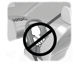
Children and Airbags
WARNING: Airbags can kill or injure a child in a child restraint. Never place a rear-facing child restraint in front of an active airbag. If you must use a forward-facing child restraint in the front seat, move the seat upon which the child restraint is installed all the way back.

Copyright © 2026 www.liaviator2.com

