Lincoln Aviator 2020-2026 Service Manual / Body and Paint / Body and Paint / Second Row Seats / Removal and Installation - Second Row Seat Folding Mechanism
Lincoln Aviator: Second Row Seats / Removal and Installation - Second Row Seat Folding Mechanism
Special Tool(s) / General Equipment
| Interior Trim Remover |
Removal
NOTE: LH (left hand) seat shown, RH (right hand) seat similar.
NOTE: Removal steps in this procedure may contain installation details.
-
-
Remove the second row seat recline handle retaining clip.
-
Remove the second row seat recline handle.
-
Remove the second row seat recline handle retaining clip.
.jpg) |
-
Remove the second row seat center valance.
-
Release the retainer.
-
Release the retainer.
-
Release the retainer.
.jpg) |
-
Remove the second row seat outboard side shield.
-
Remove the screw.
-
Detach the retainers.
Use the General Equipment: Interior Trim Remover
-
Lift the side shield and pull outward.
-
Lift the side shield and pull outward.
-
Push the side shield forward.
-
Remove the screw.
.jpg) |
-
Position aside the second row seat folding mechanism cable.
-
Remove the second row seat folding mechanism cable connector from the recline actuator.
-
Position the second row seat folding mechanism cable out of the bracket.
-
Release the second row seat folding mechanism cable pin-type retainer.
-
Remove the second row seat folding mechanism cable connector from the recline actuator.
.jpg) |
-
Remove the second row seat folding mechanism.
-
From under the seat remove the bolts.
Torque: 27 lb.in (3 Nm)
-
From under the seat remove the bolts.
.jpg) |
Installation
-
To install, reverse the removal procedure.
-
Visually inspect that the second row seat folding mechanism cable bushing is not resting on the cable connector.
.jpg) |
 Removal and Installation - Second Row Seat Cushion Blower Motor
Removal
Remove the second row single seat cushion cover.
Refer to: Second Row Single Seat Cushion Cover - Vehicles With: Second Row Captain Chairs (501-10B Second Row Seats, Removal and Installation)...
 Removal and Installation - Second Row Seat Head Restraint Guide Sleeve
Special Tool(s) /
General Equipment
Flat-Bladed Screwdriver
Removal
Second row outboard seat
Push the second row outboard seat head restraint release buttons...
Other information:
Lincoln Aviator 2020-2026 Owners Manual: Utilizing the Mediation/Arbitration Program (Canada Only)
For vehicles delivered to authorized Canadian dealers. In those cases where you continue to feel that the efforts by Ford of Canada and the authorized dealer to resolve a factory-related vehicle service concern have been unsatisfactory, Ford of Canada participates in an impartial third party mediation/arbitration program administered by the Canadian Motor Vehicle Arbitration Plan (CAMVAP)...
Lincoln Aviator 2020-2026 Service Manual: Removal and Installation - Roof Opening Panel Fixed Glass
Removal NOTE: Removal steps in this procedure may contain installation details. Place the roof opening panel shield to the fully OPEN position. On both sides. Detach part of the roof opening panel seal from the roof opening panel frame as necessary...
Categories
- Manuals Home
- Lincoln Aviator Owners Manual
- Lincoln Aviator Service Manual
- Description and Operation - Body and Frame
- Locking and Unlocking
- Disabling Auto-Start-Stop
- New on site
- Most important about car
Fastening the Seatbelts
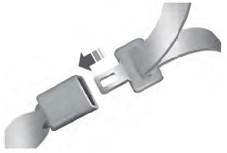
The front outboard and rear safety restraints in the vehicle are combination lap and shoulder belts.
Insert the belt tongue into the proper buckle (the buckle closest to the direction the tongue is coming from) until you hear a snap and feel it latch. Make sure that you securely fasten the tongue in the buckle.
Copyright © 2026 www.liaviator2.com
