Lincoln Aviator 2020-2026 Service Manual / Electrical / Electronic Feature Group / Side and Rear Vision
Lincoln Aviator: Electronic Feature Group / Side and Rear Vision
- Description and Operation - Blind Spot Information System - Component Location
- Description and Operation - Blind Spot Information System - Overview
- Description and Operation - Blind Spot Information System - System Operation and Component Description
- Diagnosis and Testing - Blind Spot Information System
- Removal and Installation - Side Obstacle Detection Control Module
 Removal and Installation - Head Up Display (HUD) Module
Removal
NOTE:
Removal steps in this procedure may contain installation details.
Remove the instrument panel upper section.
Refer to: Instrument Panel Upper Section (501-12 Instrument Panel and Console, Removal and Installation)...
 Description and Operation - Blind Spot Information System - Component Location
Component Location - Blind Spot Monitoring System
Item
Description
1
PDM
2
RH exterior mirror
3
SODR
4
SODL
5
DDM
6
LH exterior mirror...
Other information:
Lincoln Aviator 2020-2026 Service Manual: General Procedures - Welding Precautions
Check WARNING: Invisible ultraviolet and infrared rays emitted in welding can injure unprotected eyes and skin. Always use protection such as a welder's helmet with dark-colored filter lenses of the correct density. Electric welding will produce intense radiation, therefore, filter plate lenses of the deepest shade providing adequate visibility are recommended...
Lincoln Aviator 2020-2026 Service Manual: Removal and Installation - Upper Arm
Special Tool(s) / General Equipment 204-592Separator, Lower Arm Ball JointTKIT-2006C-FFMFLMTKIT-2006C-LMTKIT-2006C-ROW Removal NOTICE: Suspension fasteners are critical parts that affect the performance of vital components and systems...
Categories
- Manuals Home
- Lincoln Aviator Owners Manual
- Lincoln Aviator Service Manual
- Garage Door Opener
- Configuring The Head Up Display
- Tire Change Procedure
- New on site
- Most important about car
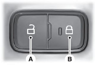
Locking and Unlocking the Doors from Inside

Locking the Doors
Press the lock switch on the door interior trim panel. The doors can no longer be released using the exterior door handle switches and the luggage compartment locks.
Copyright © 2026 www.liaviator2.com
