
Lincoln Aviator 2020-2026 Service Manual / Powertrain / Engine / Engine - 3.0L EcoBoost / Removal and Installation - Hydraulic Lash Adjuster

Lincoln Aviator: Engine - 3.0L EcoBoost / Removal and Installation - Hydraulic Lash Adjuster

Removal and Installation

  1. Refer to RH camshaft and/or LH camshaft.
    Refer to: Camshaft RH (303-01A Engine - 3.0L EcoBoost, Removal and Installation).
    Refer to: Camshaft LH (303-01A Engine - 3.0L EcoBoost, Removal and Installation).
  1. Road test the vehicle.

    Removal and Installation - Flexplate

    Removal Remove the transmission. Refer to: Transmission (307-01A Automatic Transmission - 10-Speed Automatic Transmission – 10R60, Removal). Remove the bolts and the flexplate...

    Removal and Installation - Intake Manifold

    Removal NOTICE: During engine repair procedures, cleanliness is extremely important. Any foreign material, including any material created while cleaning gasket surfaces, that enters the oil passages, coolant passages or the oil pan, can cause engine failure...

    Other information:

    Lincoln Aviator 2020-2026 Service Manual: Diagnosis and Testing - Headlamps


    Diagnostic Trouble Code (DTC) Chart Diagnostics in this manual assume a certain skill level and knowledge of Ford-specific diagnostic practices. REFER to: Diagnostic Methods (100-00 General Information, Description and Operation).   Diagnostic Trouble Code Chart Module   DTC Description Action   BCM B14E0:11 Exterior Lamps Power Supply "C": Circuit Short to Ground   GO to Pinpoint Test A   BCM B14E0:15 Exterior Lamps Power Supply "C": Circuit Short to Battery or Open   GO to Pinpoint Test A   BCM B14E1:11 Exterior Lamps Power Supply "D": Circuit Short to Ground   GO to Pinpoint Test A   BCM B14E1:15 Exterior Lamps Power Supply "D": Circuit Short to Battery or Open   GO to Pinpoint Test A   BCM B14E2:11 Exterior Lamps Power Supply "E": Circuit Short to Ground   GO to Pinpoint Test B   BCM B14E2:15 Exterior Lamps Power Supply "E": Circuit Short to Battery or Open   GO to Pinpoint Test B   BCM B14E3:11 Exterior Lamps Power Supply "F": Circuit Short to Ground   GO to Pinpoint Test B   BCM B14E3:15 Exterior Lamps Power Supply "F": Circuit Short to Battery or Open   GO to Pinpoint Test B   BCM B14E5:01 Left Front Enhanced Exterior Lighting System: General Electrical Failure   GO to Pinpoint Test S   BCM B14E5:08 Left Front Enhanced Exterior Lighting System: Bus Signal / Message Failure   GO to Pinpoint Test S   BCM B14E5:49 Left Front Enhanced Exterior Lighting System: Internal Electronic Failure   GO to Pinpoint Test S   BCM B14E5:55 Left Front Enhanced Exterior Lighting System: Not Configured   GO to Pinpoint Test S   BCM B14E7:01 Right Front Enhanced Exterior Lighting System: General Electrical Failure   GO to Pinpoint Test S   BCM B14E7:08 Right Front Enhanced Exterior Lighting System: Bus Signal / Message Failure   GO to Pinpoint Test S   BCM B14E7:49 Right Front Enhanced Exterior Lighting System: Internal Electronic Failure   GO to Pinpoint Test S   BCM B14E7:55 Right Front Enhanced Exterior Lighting System: Not Configured   GO to Pinpoint Test S   BCM B1533:02 Headlamp Switch Module: General Signal Failure   GO to Pinpoint Test A   BCM B1533:08 Headlamp Switch Module: Bus Signal / Message   GO to Pinpoint Test A   BCM B1533:49 Headlamp Switch Module: Internal Electronic Failure   GO to Pinpoint Test A   BCM B1533:56 Headlamp Switch Module: Invalid / Incompatible Configuration   GO to Pinpoint Test A   BCM B1D00:11 Left Low Beam: Circuit Short To Ground   GO to Pinpoint Test A   BCM B1D00:15 Left Low Beam: Circuit Short To Battery Or Open   GO to Pinpoint Test A   BCM B1D01:11 Right Low Beam: Circuit Short To Ground   GO to Pinpoint Test A   BCM B1D01:15 Right Low Beam: Circuit Short To Battery Or Open   GO to Pinpoint Test A   BCM B1D02:11 Left High Beam Circuit: Circuit Short To Ground   GO to Pinpoint Test B   BCM B1D02:15 Left High Beam Circuit: Circuit Short To Battery Or Open   GO to Pinpoint Test B   BCM B1D03:11 Right High Beam Circuit: Circuit Short To Ground   GO to Pinpoint Test B   BCM B1D03:15 Right High Beam Circuit: Circuit Short To Battery Or Open   GO to Pinpoint Test B   HCM B1041:04 Levelling Control: System Internal Failure   GO to Pinpoint Test H   HCM B1041:54 Levelling Control: Missing Calibration   GO to Pinpoint Test H   HCM B1087:83 LIN Bus "A": Value of Signal Protection Calculation Incorrect   GO to Pinpoint Test F   HCM B1087:83 LIN Bus "A": Value of Signal Protection Calculation Incorrect   GO to Pinpoint Test G   HCM B1087:86 LIN Bus "A": Signal Invalid   GO to Pinpoint Test F   HCM B1087:86 LIN Bus "A": Signal Invalid   GO to Pinpoint Test G   HCM B1088:83 LIN Bus "B": Value of Signal Protection Calculation Incorrect   GO to Pinpoint Test F   HCM B1088:83 LIN Bus "B": Value of Signal Protection Calculation Incorrect   GO to Pinpoint Test G   HCM B1088:86 LIN Bus "B": Signal Invalid   GO to Pinpoint Test F   HCM B1088:86 LIN Bus "B": Signal Invalid   GO to Pinpoint Test G   HCM B1437:01 Left Levelling Actuator: General Electrical Failure   GO to Pinpoint Test I   HCM B1437:87 Left Levelling Actuator: Missing Message   GO to Pinpoint Test F   HCM B1437:87 Left Levelling Actuator: Missing Message   GO to Pinpoint Test G   HCM B1439:01 Right Levelling Actuator: General Electrical Failure   GO to Pinpoint Test I   HCM B1439:87 Right Levelling Actuator: Missing Message   GO to Pinpoint Test F   HCM B1439:87 Right Levelling Actuator: Missing Message   GO to Pinpoint Test G   HCM B14D9:01 Left Headlamp Light Distribution Actuator: General Electrical Failure   GO to Pinpoint Test I   HCM B14D9:64 Left Headlamp Light Distribution Actuator: Signal Plausibility Failure   GO to Pinpoint Test I   HCM B14D9:87 Left Headlamp Light Distribution Actuator: Missing Message   GO to Pinpoint Test F   HCM B14D9:87 Left Headlamp Light Distribution Actuator: Missing Message   GO to Pinpoint Test G   HCM B14DA:01 Right Headlamp Light Distribution Actuator: General Electrical Failure   GO to Pinpoint Test I   HCM B14DA:64 Right Headlamp Light Distribution Actuator: Signal Plausibility Failure   GO to Pinpoint Test I   HCM B14DA:87 Right Headlamp Light Distribution Actuator: Missing Message   GO to Pinpoint Test F   HCM B14DA:87 Right Headlamp Light Distribution Actuator: Missing Message   GO to Pinpoint Test G   HCM B14DB:01 Left Headlamp Driver Control System: General Electrical Failure   GO to Pinpoint Test I   HCM B14DB:54 Left Headlamp Driver Control System: Missing Calibration   GO to Pinpoint Test I   HCM B14DB:55 Left Headlamp Driver Control System: Not Configured   GO to Pinpoint Test I   HCM B14DB:87 Left Headlamp Driver Control System: Missing Message   GO to Pinpoint Test F   HCM B14DB:87 Left Headlamp Driver Control System: Missing Message   GO to Pinpoint Test G   HCM B14DC:01 Right Headlamp Driver Control System: General Electrical Failure   GO to Pinpoint Test I   HCM B14DC:54 Right Headlamp Driver Control System: Missing Calibration   GO to Pinpoint Test I   HCM B14DC:55 Right Headlamp Driver Control System: Not Configured   GO to Pinpoint Test I   HCM B14DC:87 Right Headlamp Driver Control System: Missing Message   GO to Pinpoint Test F   HCM B14DC:87 Right Headlamp Driver Control System: Missing Message   GO to Pinpoint Test G   HCM B1559:96 Left Headlamp: Component Internal Failure   GO to Pinpoint Test I   HCM B155A:96 Right Headlamp: Component Internal Failure   GO to Pinpoint Test I   HCM B15A6:01 Right Matrix Controller Actuator: General Electrical Failure   GO to Pinpoint Test I   HCM B15A6:87 Right Matrix Controller Actuator: Missing Message   GO to Pinpoint Test F   HCM B15A6:87 Right Matrix Controller Actuator: Missing Message   GO to Pinpoint Test G   HCM B15A7:01 Left Matrix Controller Actuator: General Electrical Failure   GO to Pinpoint Test I   HCM B15A7:87 Left Matrix Controller Actuator: Missing Message   GO to Pinpoint Test F   HCM B15A7:87 Left Matrix Controller Actuator: Missing Message   GO to Pinpoint Test G   HCM B1A59:1C Sensor 5 Volt Supply: Circuit Voltage Out of Range   GO to Pinpoint Test H   HCM B1D64:01 Left Headlamp Swiveling Motor: General Electrical Failure   GO to Pinpoint Test I   HCM B1D64:87 Left Headlamp Swiveling Motor: Missing Message   GO to Pinpoint Test F   HCM B1D64:87 Left Headlamp Swiveling Motor: Missing Message   GO to Pinpoint Test G   HCM B1D65:01 Right Headlamp Swiveling Motor: General Electrical Failure   GO to Pinpoint Test I   HCM B1D65:87 Right Headlamp Swiveling Motor: Missing Message   GO to Pinpoint Test F   HCM B1D65:87 Right Headlamp Swiveling Motor: Missing Message   GO to Pinpoint Test G   HCM B1D68:64 Left Headlamp Swiveling Feedback Sensor: Signal Plausibility Failure   GO to Pinpoint Test I   HCM B1D69:64 Right Headlamp Swiveling Feedback Sensor: Signal Plausibility Failure   GO to Pinpoint Test I   HCM C1A03:12 Left Front Height Sensor: Circuit Short To Battery   GO to Pinpoint Test H   HCM C1A03:14 Left Front Height Sensor: Circuit Short To Ground or Open   GO to Pinpoint Test H   HCM C1A03:29 Left Front Height Sensor: Signal Invalid   GO to Pinpoint Test H   HCM C1A03:64 Left Front Height Sensor: Signal Plausibility Failure   GO to Pinpoint Test H   HCM C1A05:12 Left Rear Height Sensor: Circuit Short To Battery   GO to Pinpoint Test H   HCM C1A05:14 Left Rear Height Sensor: Circuit Short To Ground or Open   GO to Pinpoint Test H   HCM C1A05:29 Left Rear Height Sensor: Signal Invalid   GO to Pinpoint Test H   HCM C1A05:64 Left Rear Height Sensor: Signal Plausibility Failure   GO to Pinpoint Test H   HCM U0121:00 Lost Communication With Anti-Lock Brake System (ABS) Control Module: No Sub Type Information   GO to Pinpoint Test J   HCM U0146:00 Lost Communication With Serial Data Gateway "A": No Sub Type Information   GO to Pinpoint Test K   HCM U0151:00 Lost Communication With Restraints Control Module: No Sub Type Information   GO to Pinpoint Test M   HCM U0212:00 Lost Communication With Steering Column Control Module: No Sub Type Information   GO to Pinpoint Test L   HCM U023A:00 Lost Communication With Image Processing Module A: No Sub Type Information   GO to Pinpoint Test N   HCM U0415:00 Invalid Data Received From Anti-Lock Brake System (ABS) Control Module: No Sub Type Information   GO to Pinpoint Test P   HCM U0429:00 Invalid Data received from Steering Column Control Module: No Sub Type Information   GO to Pinpoint Test P   HCM U0447:00 Invalid Data Received From Serial Data Gateway "A": No Sub Type Information   GO to Pinpoint Test P   HCM U0452:00 Invalid Data Received From Restraints Control Module: No Sub Type Information   GO to Pinpoint Test P   HCM U053B:00 Invalid Data Received From Image Processing Module A: No Sub Type Information   GO to Pinpoint Test P   HCM U2024:51 Control Module Cal-Config Data: Not Programmed   GO to Pinpoint Test O   HCM U2024:57 Control Module Cal-Config Data: Invalid / Incompatible Software Component   GO to Pinpoint Test O   HCM U2100:00 Initial Configuration Not Complete: No Sub Type Information   GO to Pinpoint Test O   HCM U2101:00 Control Module Configuration Incompatible: No Sub Type Information   GO to Pinpoint Test O   HCM U2101:56 Control Module Configuration Incompatible: Invalid / Incompatible Configuration   GO to Pinpoint Test O   HCM U2101:86 Control Module Configuration Incompatible: Signal Invalid   GO to Pinpoint Test O   HCM U2200:45 Control Module Configuration Memory Corrupt: Program Memory Failure   GO to Pinpoint Test O   HCM U3000:45 Control Module: Program Memory Failure   GO to Pinpoint Test O   HCM U3000:46 Control Module: Calibration / Parameter Memory Failure   GO to Pinpoint Test O   HCM U3003:16 Battery Voltage: Circuit Voltage Below Threshold   GO to Pinpoint Test Q   HCM U3003:17 Battery Voltage: Circuit Voltage Above Threshold   GO to Pinpoint Test R   SCCM B124C:96 Turn Indicator Stalk Switch Pack: Component Internal Failure   GO to Pinpoint Test E   SCCM B124C:9E Turn Indicator Stalk Switch Pack: Stuck On   GO to Pinpoint Test E Symptom Chart Symptom Chart: Headlamps Diagnostics in this manual assume a certain skill level and knowledge of Ford-specific diagnostic practices...

    Lincoln Aviator 2020-2026 Service Manual: Diagnosis and Testing - Particulate Filter System


    Diagnostic Trouble Code (DTC) Chart Diagnostics in this manual assume a certain skill level and knowledge of Ford-specific diagnostic practices.REFER to: Diagnostic Methods (100-00 General Information, Description and Operation).   Diagnostic Trouble Code Chart Module   DTC Description Action   PCM P226D:00 Particulate Filter Deteriorated/Missing Substrate Bank 1: No Sub Type Information   GO to Pinpoint Test RA   PCM P226E:00 Particulate Filter Deteriorated/Missing Substrate Bank 2: No Sub Type Information   GO to Pinpoint Test RA   PCM P242F:00 Particulate Filter Restriction - Ash Accumulation (Bank 1): No Sub Type Information   GO to Pinpoint Test RA   PCM P243A:00 Particulate Filter Restriction - Ash Accumulation (Bank 2): No Sub Type Information   GO to Pinpoint Test RA   PCM P243B:00 Particulate Filter Restriction - Forced Limited Power (Bank 2): No Sub Type Information   GO to Pinpoint Test RA   PCM P2452:00 Particulate Filter Pressure Sensor A Circuit: No Sub Type Information   GO to Pinpoint Test RC   PCM P2453:00 Particulate Filter Pressure Sensor A Circuit Range/Performance: No Sub Type Information   GO to Pinpoint Test RC   PCM P2454:00 Particulate Filter Pressure Sensor A Circuit Low: No Sub Type Information   GO to Pinpoint Test RC   PCM P2455:00 Particulate Filter Pressure Sensor A Circuit High: No Sub Type Information   GO to Pinpoint Test RC   PCM P2456:00 Particulate Filter Pressure Sensor Circuit A Intermittent/Erratic: No Sub Type Information   GO to Pinpoint Test RC   PCM P245E:00 Particulate Filter Pressure Sensor B Circuit: No Sub Type Information   GO to Pinpoint Test RC   PCM P245F:00 Particulate Filter Pressure Sensor B Circuit Range/Performance: No Sub Type Information   GO to Pinpoint Test RC   PCM P2460:00 Particulate Filter Pressure Sensor B Circuit Low: No Sub Type Information   GO to Pinpoint Test RC   PCM P2461:00 Particulate Filter Pressure Sensor B Circuit High: No Sub Type Information   GO to Pinpoint Test RC   PCM P2462:00 Particulate Filter Pressure Sensor Circuit B Intermittent/Erratic: No Sub Type Information   GO to Pinpoint Test RC   PCM P246C:00 Particulate Filter Restriction - Forced Limited Power (Bank 1): No Sub Type Information   GO to Pinpoint Test RA   PCM P2CE5:00 Particulate Filter Pressure Sensor C Circuit: No Sub Type Information   GO to Pinpoint Test RC   PCM P2CE6:00 Particulate Filter Pressure Sensor C Circuit Range/Performance: No Sub Type Information   GO to Pinpoint Test RC   PCM P2CE7:00 Particulate Filter Pressure Sensor C Circuit Low: No Sub Type Information   GO to Pinpoint Test RC   PCM P2CE8:00 Particulate Filter Pressure Sensor C Circuit High: No Sub Type Information   GO to Pinpoint Test RC   PCM P2CE9:00 Particulate Filter Pressure Sensor Circuit C Intermittent/Erratic: No Sub Type Information   GO to Pinpoint Test RC   PCM P2CEA:00 Particulate Filter Pressure Sensor D Circuit: No Sub Type Information   GO to Pinpoint Test RC   PCM P2CEB:00 Particulate Filter Pressure Sensor D Circuit Range/Performance: No Sub Type Information   GO to Pinpoint Test RC   PCM P2CEC:00 Particulate Filter Pressure Sensor D Circuit Low: No Sub Type Information   GO to Pinpoint Test RC   PCM P2CED:00 Particulate Filter Pressure Sensor D Circuit High: No Sub Type Information   GO to Pinpoint Test RC   PCM P2CEE:00 Particulate Filter Pressure Sensor Circuit D Intermittent/Erratic: No Sub Type Information   GO to Pinpoint Test RC   PCM U0601:00 Lost Communication With Particulate Filter Pressure Sensor A: No Sub Type Information   GO to Pinpoint Test RC   PCM U0602:00 Lost Communication With Particulate Filter Pressure Sensor B: No Sub Type Information   GO to Pinpoint Test RC   PCM U0696:00 Lost Communication With Particulate Filter Pressure Sensor C: No Sub Type Information   GO to Pinpoint Test RC   PCM U0697:00 Lost Communication With Particulate Filter Pressure Sensor D: No Sub Type Information   GO to Pinpoint Test RC Global Customer Symptom Code (GCSC) Chart Diagnostics in this manual assume a certain skill level and knowledge of Ford-specific diagnostic practices...

    Categories

    Fastening the Seatbelts

    The front outboard and rear safety restraints in the vehicle are combination lap and shoulder belts.

    Insert the belt tongue into the proper buckle (the buckle closest to the direction the tongue is coming from) until you hear a snap and feel it latch. Make sure that you securely fasten the tongue in the buckle.
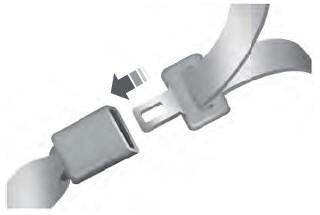
    Lincoln Aviator. Fastening the Seatbelts

    To unfasten, press the release button and remove the tongue from the buckle.

    read more

     
    Copyright © 2026 www.liaviator2.com