
Lincoln Aviator: Rear View Mirrors / Removal and Installation - Interior Rear View Mirror
Removal
NOTE:
Removal steps in this procedure may contain installation details.
-
Release the clips and remove the IPMA cover.
-
Disconnect the interior rear view mirror electrical connector.
-
Remove the interior rear view mirror.
-
Loosen the set screw.
Torque:
17 lb.in (1.9 Nm)
-
Slide the interior rear view mirror upward.
Installation
-
To install, reverse the removal procedure.
Special Tool(s) /
General Equipment
Flat Headed Screw Driver
Removal
NOTE:
Removal steps in this procedure may contain installation details...
Other information:
Diagnostic Trouble Code (DTC) Chart
Diagnostics in this manual assume a certain skill level and knowledge of Ford-specific diagnostic practices. REFER to: Diagnostic Methods (100-00 General Information, Description and Operation).
Diagnostic Trouble Code Chart
Module
DTC
Description
Action
BCM
B1551:51
Phone As A Key: Not Programmed
GO to Pinpoint Test G
BCM
B155E:00
Incorrect Response from Immobilizer SubControl Module: No Sub Type Information
GO to Pinpoint Test M
RFA
B1589:29
Antenna #3: Signal Invalid
GO to Pinpoint Test A
RFA
B1589:31
Antenna #3: No Signal
GO to Pinpoint Test A
RFA
B1589:45
Antenna #3: Program Memory Failure
GO to Pinpoint Test A
RFA
B1589:49
Antenna #3: Internal Electronic Failure
GO to Pinpoint Test A
RFA
B1589:57
Antenna #3: Invalid/ Incompatible Software Component
GO to Pinpoint Test A
RFA
B1590:29
Antenna #4: Signal Invalid
GO to Pinpoint Test A
RFA
B1590:31
Antenna #4: No Signal
GO to Pinpoint Test A
RFA
B1590:45
Antenna #4: Program Memory Failure
GO to Pinpoint Test A
RFA
B1590:49
Antenna #4: Internal Electronic Failure
GO to Pinpoint Test A
RFA
B1590:57
Antenna #4: Invalid/ Incompatible Software Component
GO to Pinpoint Test A
RFA
B1591:29
Antenna #5: Signal Invalid
GO to Pinpoint Test B
RFA
B1591:31
Antenna #5: No Signal
GO to Pinpoint Test B
RFA
B1591:45
Antenna #5: Program Memory Failure
GO to Pinpoint Test B
RFA
B1591:49
Antenna #5: Internal Electronic Failure
GO to Pinpoint Test B
RFA
B1591:57
Antenna #5: Invalid/ Incompatible Software Component
GO to Pinpoint Test B
RFA
B1592:29
Antenna #6: Signal Invalid
GO to Pinpoint Test B
RFA
B1592:31
Antenna #6: No Signal
GO to Pinpoint Test B
RFA
B1592:45
Antenna #6: Program Memory Failure
GO to Pinpoint Test B
RFA
B1592:49
Antenna #6: Internal Electronic Failure
GO to Pinpoint Test B
RFA
B1592:57
Antenna #6: Invalid/ Incompatible Software Component
GO to Pinpoint Test B
RFA
B1593:29
Antenna #7: Signal Invalid
GO to Pinpoint Test C
RFA
B1593:31
Antenna #7: No Signal
GO to Pinpoint Test C
RFA
B1593:45
Antenna #7: Program Memory Failure
GO to Pinpoint Test C
RFA
B1593:49
Antenna #7: Internal Electronic Failure
GO to Pinpoint Test C
RFA
B1593:57
Antenna #7: Invalid/ Incompatible Software Component
GO to Pinpoint Test C
RFA
B1594:29
Antenna #8: Signal Invalid
GO to Pinpoint Test B
RFA
B1594:31
Antenna #8: No Signal
GO to Pinpoint Test B
RFA
B1594:45
Antenna #8: Program Memory Failure
GO to Pinpoint Test B
RFA
B1594:49
Antenna #8: Internal Electronic Failure
GO to Pinpoint Test B
RFA
B1594:57
Antenna #8: Invalid/ Incompatible Software Component
GO to Pinpoint Test B
RFA
B1595:29
Antenna #9: Signal Invalid
GO to Pinpoint Test C
RFA
B1595:31
Antenna #9: No Signal
GO to Pinpoint Test C
RFA
B1595:45
Antenna #9: Program Memory Failure
GO to Pinpoint Test C
RFA
B1595:49
Antenna #9: Internal Electronic Failure
GO to Pinpoint Test C
RFA
B1595:57
Antenna #9: Invalid/ Incompatible Software Component
GO to Pinpoint Test C
RFA
B1596:29
Antenna #10: Signal Invalid
GO to Pinpoint Test C
RFA
B1596:31
Antenna #10: No Signal
GO to Pinpoint Test C
RFA
B1596:45
Antenna #10: Program Memory Failure
GO to Pinpoint Test C
RFA
B1596:49
Antenna #10: Internal Electronic Failure
GO to Pinpoint Test C
RFA
B1596:57
Antenna #10: Invalid/ Incompatible Software Component
GO to Pinpoint Test C
RFA
B1597:29
Antenna #11: Signal Invalid
GO to Pinpoint Test D
RFA
B1597:31
Antenna #11: No Signal
GO to Pinpoint Test D
RFA
B1597:45
Antenna #11: Program Memory Failure
GO to Pinpoint Test D
RFA
B1597:49
Antenna #11: Internal Electronic Failure
GO to Pinpoint Test D
RFA
B1597:57
Antenna #11: Invalid/ Incompatible Software Component
GO to Pinpoint Test D
RFA
B15A5:56
Bluetooth Low Energy Module: Invalid/ Incompatible Configuration
GO to Pinpoint Test E
RFA
B1A56:29
Antenna: Signal Invalid
GO to Pinpoint Test A
RFA
B1A56:31
Antenna: No Signal
GO to Pinpoint Test A
RFA
B1A56:45
Antenna: Program Memory Failure
GO to Pinpoint Test A
RFA
B1A56:49
Antenna: Internal Electronic Failure
GO to Pinpoint Test A
RFA
B1A56:57
Antenna: Invalid/ Incompatible Software Component
GO to Pinpoint Test A
RFA
B1D55:29
Antenna #2: Signal Invalid
GO to Pinpoint Test D
RFA
B1D55:31
Antenna #2: No Signal
GO to Pinpoint Test D
RFA
B1D55:45
Antenna #2: Program Memory Failure
GO to Pinpoint Test D
RFA
B1D55:49
Antenna #2: Internal Electronic Failure
GO to Pinpoint Test D
RFA
B1D55:57
Antenna #2: Invalid/ Incompatible Software Component
GO to Pinpoint Test D
RFA
P0601:41
Internal Control Module Memory Checksum Error: General Checksum Failure
GO to Pinpoint Test K
RFA
P1269:00
Immobilizer Code Not Programmed: No Sub Type Information
GO to Pinpoint Test G
RFA
P1602:00
Immobilizer/ ECM Communication Error: No Sub Type Information
GO to Pinpoint Test G
RFA
P1622:00
Immobilizer ID Does Not Match: No Sub Type Information
GO to Pinpoint Test G
RFA
P1623:00
Immobilizer Code Word/ID Number Write Failure: No Sub Type Information
GO to Pinpoint Test G
RFA
U0146:08
Lost Communication With Gateway "A": Bus Signal/Message Failure
GO to Pinpoint Test L
RFA
U0198:00
Lost Communication With Telematic Control Module: No Sub Type Information
GO to Pinpoint Test L
RFA
U0422:00
Invalid Data Received From Body Control Module: No Sub Type Information
GO to Pinpoint Test G
RFA
U200D:11
Control Module Output Power A: Circuit Short to Ground
GO to Pinpoint Test A
RFA
U200D:15
Control Module Output Power A: Circuit Short to Battery or Open
GO to Pinpoint Test A
RFA
U200E:11
Control Module Output Power B: Circuit Short to Ground
GO to Pinpoint Test B
RFA
U200E:15
Control Module Output Power B: Circuit Short to Battery or Open
GO to Pinpoint Test B
RFA
U200F:11
Control Module Output Power C: Circuit Short to Ground
GO to Pinpoint Test C
RFA
U200F:15
Control Module Output Power C: Circuit Short to Battery or Open
GO to Pinpoint Test C
RFA
U201A:06
Control Module Main Calibration Data: Algorithm Based Failure
GO to Pinpoint Test F
RFA
U201A:46
Control Module Main Calibration Data: Calibration/ Parameter Memory failure
GO to Pinpoint Test F
RFA
U201A:55
Control Module Main Calibration Data: Not Configured
GO to Pinpoint Test F
RFA
U2100:55
Initial Configuration Not Complete: Not Configured
GO to Pinpoint Test F
RFA
U3000:42
Control Module: General Memory Failure
GO to Pinpoint Test K
RFA
U3000:44
Control Module: Data Memory Failure
GO to Pinpoint Test K
RFA
U3000:49
Control Module: Internal Electronic Failure
GO to Pinpoint Test K
RFA
U3003:16
Battery Voltage: Circuit Voltage Below Threshold
GO to Pinpoint Test I
RFA
U3003:17
Battery Voltage: Circuit Voltage Above Threshold
GO to Pinpoint Test J
Symptom Chart
Symptom Chart: PATS
Diagnostics in this manual assume a certain skill level and knowledge of Ford-specific diagnostic practices...
System Operation
System Diagram - Supplemental Restraint System (SRS)
Item
Description
1
RCM
2
Ignition Switch
3
GWM
4
Driver Seatbelt Buckle Switch
5
Passenger Seatbelt Buckle Switch
6
RHFront Impact Severity Sensor
7
Driver Door Side Impact Sensor
8
Driver C-Pillar Side Impact Sensor
9
Passenger Belt Tension Sensor (BTS)
10
Passenger Seat Position Sensor
11
Driver Seat Position Sensor
12
APIM
13
Passenger Door Side Impact Sensor
14
BCM
15
Driver Second Row Seatbelt Buckle Switch
16
Passenger Second Row Seatbelt Buckle Switch
17
LH Front Impact Severity Sensor
18
OCSM
19
Center Second Row Seatbelt Buckle Switch
20
Passenger C-Pillar Side Impact Sensor
21
Driver Third Row Seatbelt Buckle Switch
22
Passenger Third Row Seatbelt Buckle Switch
23
IPC
Item
Description
1
Passenger Seatbelt Anchor Pretensioner
2
Driver Seatbelt Anchor Pretensioner
3
Driver Seatbelt Retractor Pretensioner
4
Passenger Side Curtain Airbag
5
Driver Side Curtain Airbag
6
Passenger Side Airbag
7
Driver Side Airbag
8
Passenger Airbag (Stages 1 and 2)
9
Driver Airbag (Stages 1 and 2)
10
RCM
11
BCM
12
Passenger Seatbelt Adaptive Load Limiter
13
Passenger Seatbelt Retractor Pretensioner
14
Passenger Load Limiting Retractor
15
Passenger Airbag Vent (if equipped)
16
Passenger Knee Airbag
17
Driver Knee Airbag
18
Driver Second Row Seatbelt Retractor
19
Passenger Second Row Seatbelt Retractor
Network Message Chart - Supplemental Restraint System (SRS)
Module Network Input Messages - RCM
Broadcast Message
Originating Module
Message Purpose
eCall confirmation
APIM
Used for SYNC® 911 Assist™ operation...
Categories
The front outboard and rear safety restraints
in the vehicle are combination lap and
shoulder belts.
Insert the belt tongue into the proper
buckle (the buckle closest to the direction
the tongue is coming from) until you hear
a snap and feel it latch. Make sure that
you securely fasten the tongue in the
buckle.
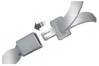
To unfasten, press the release button
and remove the tongue from the buckle.
read more