Lincoln Aviator: Exterior Lighting / Removal and Installation - Light Emitting Diode (LED) Control Module
Removal
NOTE: The high series headlamp assembly comes with two light emitting diode (LED) control modules. The low series with one light emitting diode (LED) control module.
NOTE: Removal steps in this procedure may contain installation details.
Bottom mounted light emitting diode (LED) control module
-
Remove the headlamp assembly.
Refer to: Headlamp Assembly (417-01 Exterior Lighting, Removal and Installation).
-
Remove the bottom mounted light emitting diode LED control module screws.
.jpg) |
-
NOTE: The light emitting diode LED control module electrical connector is mounted in the headlamp assembly. It will self disconnect or connect during removal or installation.
NOTE: Note the position of the light emitting diode LED control module electrical connector to the light emitting diode LED control module for installation.
Remove the bottom mounted light emitting diode LED control module.
.jpg) |
Top mounted light emitting diode (LED) control module
NOTE: LH side shown, RH side similar.
-
Remove the pin type retainers and the radiator sight shield.
.jpg) |
-
Remove the screws and position the top mounted light emitting diode LED control module.
.jpg) |
-
Disconnect the electrical connectors and remove the top mounted light emitting diode LED control module.
.jpg) |
Installation
-
To install, reverse the removal procedure.
-
NOTE: Carry out this step only when a LED headlamp module is being replaced.
Using a diagnostic scan tool, perform the BCM - LIN New Module Initialization. Follow the diagnostic scan tool directions.
 Removal and Installation - High Mounted Stoplamp
Removal
NOTE:
Removal steps in this procedure may contain installation details.
Remove the rear spoiler.
Refer to: Rear Spoiler (501-08 Exterior Trim and Ornamentation, Removal and Installation)...
 Removal and Installation - Light Sensor
Removal
NOTE:
Removal steps in this procedure may contain installation details.
Using a non-marring tool release and position the light sensor...
Other information:
Lincoln Aviator 2020-2026 Service Manual: Removal and Installation - Condenser Inlet Line - 3.0L EcoBoost
Removal NOTICE: During the removal of components, cap, tape or otherwise appropriately protect all openings to prevent the ingress of dirt or other contamination. Remove protective materials prior to installation. NOTE: Removal steps in this procedure may contain installation details...
Lincoln Aviator 2020-2026 Service Manual: Removal and Installation - Transmission Fluid Auxiliary Pump
Removal NOTE: It is not necessary to remove the transmission fluid filter to remove the transmission fluid auxiliary pump. Remove the transmission fluid pan and gasket. Refer to: Transmission Fluid Pan, Gasket and Filter (307-01A Automatic Transmission - 10-Speed Automatic Transmission – 10R60, Removal and Installation)...
Categories
- Manuals Home
- Lincoln Aviator Owners Manual
- Lincoln Aviator Service Manual
- Wireless Accessory Charger (If Equipped)
- Child Safety Locks
- Interior Lamps
- New on site
- Most important about car
Fastening the Seatbelts
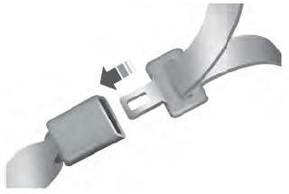
The front outboard and rear safety restraints in the vehicle are combination lap and shoulder belts.
Insert the belt tongue into the proper buckle (the buckle closest to the direction the tongue is coming from) until you hear a snap and feel it latch. Make sure that you securely fasten the tongue in the buckle.