Lincoln Aviator 2020-2026 Service Manual / Electrical / Information and Entertainment Systems / Information and Entertainment System - General Information / Removal and Installation - Rear Audio Control Module (RACM)
Lincoln Aviator: Information and Entertainment System - General Information / Removal and Installation - Rear Audio Control Module (RACM)
Removal
NOTE: Removal steps in this procedure may contain installation details.
NOTE: Touchscreen controls shown, analog controls are similar.
-
NOTE: If installing a new module, it is necessary to upload the module configuration information to the scan tool prior to removing the module. This information must be downloaded into the new module after installation.
Using a diagnostic scan tool, begin the PMI process for the RACM following the on-screen instructions.
-
NOTE: On both sides.
Release the clips and position the floor console top side trim panels.
.jpg) |
-
Release the clips, disconnect the electrical connector and remove the rear console trim plate.
.jpg) |
-
Remove the screws and the RACM.
.jpg) |
Installation
-
To install, reverse the removal procedure.
-
NOTE: This step is only necessary when installing a new component.
Using a diagnostic scan tool, complete the PMI process for the RACM following the on-screen instructions.
 Removal and Installation - Overhead Speaker
Removal
NOTE:
Removal steps in this procedure may contain installation details.
NOTE:
LH front speaker is shown, all others are similar.
Lower the headliner...
 Removal and Installation - Rear Door Speaker
Removal
NOTE:
Removal steps in this procedure may contain installation details.
All vehicles
Remove the rear door trim panel.
Refer to: Rear Door Trim Panel (501-05 Interior Trim and Ornamentation, Removal and Installation)...
Other information:
Lincoln Aviator 2020-2026 Service Manual: Diagnosis and Testing - Daytime Running Lamps (DRL)
Symptom Charts Symptom Chart: DRL Diagnostics in this manual assume a certain skill level and knowledge of Ford-specific diagnostic practices. REFER to: Diagnostic Methods (100-00 General Information, Description and Operation). NOTE: Before beginning diagnostics, refer to Description and Operation in this section for proper DRL operation...
Lincoln Aviator 2020-2026 Owners Manual: Manual Zoom
WARNING: When manual zoom is on, the full area behind your vehicle may not show. Be aware of your surroundings when using the manual zoom feature. Note: Manual zoom is only available when the transmission is in reverse (R). Note: When you enable manual zoom, only the centerline is shown...
Categories
- Manuals Home
- Lincoln Aviator Owners Manual
- Lincoln Aviator Service Manual
- Child Safety Locks
- Remove and Reinstall the Battery
- Description and Operation - Body and Frame
- New on site
- Most important about car
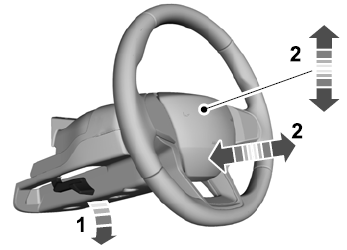
Adjusting the Steering Wheel - Vehicles With: Manual Adjustable Steering Column
WARNING: Do not adjust the steering wheel when your vehicle is moving.
Note: Make sure that you are sitting in the correct position.
Unlock the steering column. Adjust the steering wheel to the desired position.
Copyright © 2026 www.liaviator2.com
