Lincoln Aviator: Rear Drive Halfshafts / Removal and Installation - Rear Halfshaft
Removal
NOTICE: Never pick up or hold the halfshaft by only the inner or outer CV joint. Damage to the CV joint will occur.
NOTICE: Never use a hammer to remove or install the halfshafts. Damage to the CV joint may occur.
NOTICE: Never use the halfshaft assembly as a lever to position other components. Damage to the halfshaft or CV joint may occur.
NOTICE: Do not allow the boots to contact sharp edges or hot exhaust components. Damage to the halfshaft boots will occur.
NOTICE: Do not drop assembled halfshafts. The impact may cut the boots from the inside without evidence of external damage.
NOTE: LH shown RH similar.
-
Remove the wheel knuckle.
Refer to: Wheel Knuckle (204-02 Rear Suspension, Removal and Installation).
-
Using a pry bar, remove the halfshaft.
.jpg) |
-
Remove and discard the inner halfshaft circlip.
.jpg) |
-
Clean and inspect the inner halfshaft seal surface and splines for damage.
.jpg) |
-
Clean and inspect the outer CV (constant velocity) housing at the shown locations.
.jpg) |
Installation
NOTE: LH shown RH similar.
-
NOTE: The halfshaft seal has to be replaced whenever the halfshaft is removed.
Replace the halfshaft seal.
Refer to: Rear Halfshaft Seal (205-02 Rear Drive Axle/Differential, Removal and Installation).
-
Install a new inner halfshaft circlip.
.jpg) |
-
NOTICE: After insertion, pull the halfshaft inner end to make sure the circlip is locked.
NOTE: Make sure that the circlip opening is located at the bottom or 6 o'clock position to allow easy halfshaft installation.
NOTE: When seated correctly, the halfshaft retainer circlip can be felt as it snaps into the differential side gear groove.
Install the halfshaft until the halfshaft circlip is fully seated.
.jpg) |
-
Install the wheel knuckle.
Refer to: Wheel Knuckle (204-02 Rear Suspension, Removal and Installation).
-
Check and top off the rear differential fluid.
Refer to: Differential Fluid Level Check (205-02 Rear Drive Axle/Differential, General Procedures).
 Diagnosis and Testing - Rear Drive Halfshafts
Preliminary Inspection
Visually inspect the CV joints, housing, boots, and clamps for obvious signs of mechanical damage.
If an obvious cause for an observed or reported concern is
found, correct the cause (if possible) before proceeding to the next
step
If the cause is not visually evident, verify the symptom and REFER to Symptom Chart: NVH...
 Brake System
..
Other information:
Lincoln Aviator 2020-2026 Owners Manual: Engine Specifications - Excluding: Plug-In Hybrid Electric Vehicle (PHEV)
..
Lincoln Aviator 2020-2026 Service Manual: Description and Operation - Body and Frame
The body consists of the following: Front bumper constructed of high-strength aluminum Rear bumper constructed of Boron and HSLA ultra high-strength steels Front frame rails constructed of high-strength aluminum Rear frame rails constructed of Boron ultra high-strength steel Fender reinforcement tube constructed of Dual Phase (DP) 800 high-strength steel Cast aluminum fender apron assembly Liftgate outer panel constructed of mild steel Body structure constructed of Boron, Dual Phase (DP) and high-strength steels Roof panel reinforcements constructed of Dual Phase (DP) 600 and mild steel Bolted, removable front fenders, hinged doors and hood Bodyside outer panels constructed of mild steel Steel hood hinges Mastic pads used on floor pan for sound deadening Front End Panel Margining NOTE: Margining specifications apply to left hand (LH) and right hand (RH) side of the vehicle unless stated...
Categories
- Manuals Home
- Lincoln Aviator Owners Manual
- Lincoln Aviator Service Manual
- USB Port and Power Point Locations
- Child Safety Locks
- Wireless Accessory Charger (If Equipped)
- New on site
- Most important about car
Activating Intelligent Access
The intelligent access key must be within 3 ft (1 m) of the door or luggage compartment you intend to lock or unlock.
At a Door
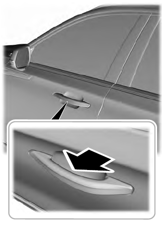
Electronic door handles are on each door. Gently depress the switch inside the exterior door handle to unlock and open the door. An unlock symbol illuminates on the door window trim indicating your vehicle is unlocked.

