Lincoln Aviator 2020-2026 Service Manual / Electrical / Climate Control System / Rear Climate Control / Removal and Installation - Rear Heater Core
Lincoln Aviator: Rear Climate Control / Removal and Installation - Rear Heater Core
Special Tool(s) / General Equipment
| Hose Clamp Remover/Installer |
Removal
NOTE: Removal steps in this procedure may contain installation details.
-
Drain the cooling system.
Refer to: Engine Cooling System Draining, Vacuum Filling and Bleeding (303-03A Engine Cooling - 3.0L EcoBoost, General Procedures).
Refer to: Engine Cooling System Draining, Vacuum Filling and Bleeding (303-03A Engine Cooling - 3.0L EcoBoost, General Procedures).
-
Remove the RHR wheel and tire.
Refer to: Wheel and Tire (204-04A Wheels and Tires, Removal and Installation).
-
Remove the retainers and position aside RHR wheel splashshield.
.jpg) |
-
Release clamp and position aside coolant line.
Use the General Equipment: Hose Clamp Remover/Installer
.jpg) |
-
Remove the RH loadspace trim panel.
Refer to: Loadspace Trim Panel (501-05 Interior Trim and Ornamentation, Removal and Installation).
-
-
Remove and discard the heater core clamps, position aside the heater core inlet and outlet tubes.
-
Replace the heater core inlet and outlet tubes o-seals.
-
Remove the retainers and the rear heater core access cover.
-
Remove and discard the heater core clamps, position aside the heater core inlet and outlet tubes.
.jpg) |
-
Remove the rear heater core.
.jpg) |
Installation
-
To install, reverse the removal procedure.
-
NOTE: Replace the pass-through floor seal with new if seal is removed or damaged.
If replacing the heater core inlet and outlet tubes, the rear climate control housing must be removed.
Refer to: Rear Climate Control Housing (412-02A Rear Climate Control, Removal and Installation).
-
Fill and bleed the cooling system.
Refer to: Engine Cooling System Draining, Vacuum Filling and Bleeding (303-03A Engine Cooling - 3.0L EcoBoost, General Procedures).
Refer to: Engine Cooling System Draining, Vacuum Filling and Bleeding (303-03A Engine Cooling - 3.0L EcoBoost, General Procedures).
 Removal and Installation - Rear Footwell Air Discharge Temperature Sensor
Removal
NOTE:
Removal steps in this procedure may contain installation details.
Remove the RH loadspace trim panel.
Refer to: Loadspace Trim Panel (501-05 Interior Trim and Ornamentation, Removal and Installation)...
 Removal and Installation - Rear Heater Core Inlet Line
Removal
NOTE:
The rear heater core inlet line is installed from the
factory as a one-piece assembly. The replacement part is supplied as an
assembly, containing the rear heater core outlet line and the rear
evaporator inlet and outlet lines...
Other information:
Lincoln Aviator 2020-2026 Owners Manual: Rollover Warning
WARNING: Utility vehicles have a significantly higher rollover rate than other types of vehicles. WARNING: Vehicles with a higher center of gravity (utility and four-wheel drive vehicles) handle differently than vehicles with a lower center of gravity (passenger cars)...
Lincoln Aviator 2020-2026 Service Manual: Diagnosis and Testing - Turn Signal and Hazard Lamps
Diagnostic Trouble Code (DTC) Chart Diagnostics in this manual assume a certain skill level and knowledge of Ford-specific diagnostic practices. REFER to: Diagnostic Methods (100-00 General Information, Description and Operation). Diagnostic Trouble Code Chart Module DTC Description Action BCM B123A:11 Left Front Turn Indicator:Circuit Short To Ground GO to Pinpoint Test C BCM B123A:15 Left Front Turn Indicator:Circuit Short To Battery Or Open GO to Pinpoint Test C BCM B123B:11 Right Front Turn Indicator:Circuit Short To Ground GO to Pinpoint Test C BCM B123B:15 Right Front Turn Indicator:Circuit Short To Battery Or Open GO to Pinpoint Test C BCM B1247:11 Left Rear Turn Indicator:Circuit Short To Ground GO to Pinpoint Test D BCM B1247:15 Left Rear Turn Indicator:Circuit Short To Battery or Open GO to Pinpoint Test D BCM B1248:11 Right Rear Turn Indicator:Circuit Short To Ground GO to Pinpoint Test D BCM B1248:15 Right Rear Turn Indicator:Circuit Short To Battery or Open GO to Pinpoint Test D BCM B1265:01 Left Rear Turn Lamp Feedback:General Electrical Failure GO to Pinpoint Test G BCM B1266:01 Right Rear Turn Lamp Feedback:General Electrical Failure GO to Pinpoint Test G BCM B1497:01 Left Front Turn Lamp Feedback:General Electrical Failure GO to Pinpoint Test G BCM B1498:01 Right Front Turn Lamp Feedback:General Electrical Failure GO to Pinpoint Test G BCM B1D35:11 Hazard Switch:Circuit Short to Ground GO to Pinpoint Test F DDM B1D06:11 Left Turn Indicator:Circuit Short To Ground GO to Pinpoint Test E DDM B1D06:15 Left Turn Indicator:Circuit Short To Battery Or Open GO to Pinpoint Test E PDM B1D07:11 Right Turn Indicator:Circuit Short To Ground GO to Pinpoint Test E PDM B1D07:15 Right Turn Indicator:Circuit Short To Battery Or Open GO to Pinpoint Test E SCCM B124C:96 Turn Indicator Stalk Switch Pack:Component Internal Failure GO to Pinpoint Test H SCCM B124C:9E Turn Indicator Stalk Switch Pack:Stuck On GO to Pinpoint Test H Symptom Chart(s) Symptom Chart: Turn Signal and Hazard Lamps Diagnostics in this manual assume a certain skill level and knowledge of Ford-specific diagnostic practices...
Categories
- Manuals Home
- Lincoln Aviator Owners Manual
- Lincoln Aviator Service Manual
- Tire Change Procedure
- Remove and Reinstall the Battery
- Locking and Unlocking
- New on site
- Most important about car
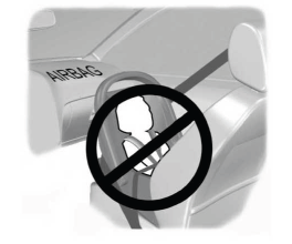
Children and Airbags
WARNING: Airbags can kill or injure a child in a child restraint. Never place a rear-facing child restraint in front of an active airbag. If you must use a forward-facing child restraint in the front seat, move the seat upon which the child restraint is installed all the way back.

Copyright © 2026 www.liaviator2.com
