Lincoln Aviator 2020-2025 Service Manual / Electrical / Battery and Charging System / Generator and Regulator / Removal and Installation - Starter Generator - 3.0L EcoBoost – Hybrid (BQ)
Lincoln Aviator: Generator and Regulator / Removal and Installation - Starter Generator - 3.0L EcoBoost – Hybrid (BQ)
Special Tool(s) / General Equipment
| Locking Pliers |
Removal
NOTE: Removal steps in this procedure may contain installation details.
-
With the vehicle in NEUTRAL, position it on a hoist.
Refer to: Jacking and Lifting (100-02 Jacking and Lifting, Description and Operation).
-
Disconnect the batteries.
Refer to: Battery Disconnect and Connect (414-01 Battery, Mounting and Cables, General Procedures).
-
Remove the RHF wheel and tire assembly.
Refer to: Wheel and Tire (204-04A Wheels and Tires, Removal and Installation).
-
Remove the pushpins and the RHF inner splash shield.
.jpg) |
-
NOTICE: When installing the B+ terminal nut to the generator, finger-start the nut before tightening or component damage may occur.
Position the generator B+ wire terminal protective cover aside, remove the nut and position the generator B+ wire aside. Disconnect the generator electrical connector. Detach the retainer and position the wire harness aside.
Torque: 155 lb.in (17.5 Nm)
.jpg) |
-
Remove the accessory drive belt tensioner.
Refer to: Accessory Drive Belt Tensioner (303-05B Accessory Drive - 3.0L EcoBoost – Hybrid (BQ), Removal and Installation).
-
-
Using hose locking pliers, clamp the upper radiator coolant hose.
Use the General Equipment: Locking Pliers
-
Loosen the clamp and disconnect the upper radiator coolant hose.
Torque: 48 lb.in (5.4 Nm)
-
Detach the retainer and position the upper radiator coolant hose aside.
-
Using hose locking pliers, clamp the upper radiator coolant hose.
.jpg) |
-
Detach the wire harness retainer from the starter generator.
.jpg) |
-
-
Remove the starter generator nut.
Torque: 35 lb.ft (47.5 Nm)
-
Remove the starter generator bolt.
Torque: 35 lb.ft (47.5 Nm)
-
Remove the stud and the starter generator.
Torque: 71 lb.in (8 Nm)
-
Remove the starter generator nut.
.jpg) |
Installation
-
To install, reverse the removal procedure.
-
Bleed the engine cooling system.
Refer to: Cooling System Filling and Bleeding (303-03C Electric Powertrain Cooling - 3.0L EcoBoost – Hybrid (BQ), General Procedures).
 Removal and Installation - Generator Pulley
Removal
WARNING:
Before beginning any service procedure in this
section, refer to Safety Warnings in section 100-00 General Information...
Other information:
Lincoln Aviator 2020-2025 Service Manual: Removal and Installation - Tie Rod
Special Tool(s) / General Equipment Boot Clamp Pliers Materials Name Specification Motorcraft® Premium Long-Life GreaseXG-1-E1 ESA-M1C75-B Removal NOTICE: When servicing inner tie rods, install a new bellows boot and clamps...
Lincoln Aviator 2020-2025 Owners Manual: Garage Door Opener
HomeLink Wireless Control System WARNING: Do not use the system with any garage door opener that does not have the safety stop and reverse feature as required by U.S. Federal Safety Standards (this includes any garage door opener manufactured before April 1, 1982)...
Categories
- Manuals Home
- Lincoln Aviator Owners Manual
- Lincoln Aviator Service Manual
- Description and Operation - Jacking and Lifting
- Opening and Closing the Hood
- Keyless Entry
- New on site
- Most important about car
Child Safety Locks
When the child safety locks are set, you cannot open the rear doors from the inside.

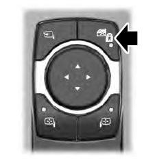
The child safety lock control is on the driver door.
Press the control to switch the child safety locks on. Press the control again to switch them off. A light on the child safety control illuminates when you switch them on.
Copyright © 2025 www.liaviator2.com

