Lincoln Aviator: Generator and Regulator / Removal and Installation - Generator Pulley
Removal
-
Follow the health and safety precautions..jpg) WARNING:
Before beginning any service procedure in this
section, refer to Safety Warnings in section 100-00 General Information.
Failure to follow this instruction may result in serious personal
injury.
WARNING:
Before beginning any service procedure in this
section, refer to Safety Warnings in section 100-00 General Information.
Failure to follow this instruction may result in serious personal
injury.
Refer to: Health and Safety Precautions (100-00 General Information, Description and Operation).
-
Remove the generator.
Refer to: Generator - 3.0L EcoBoost (414-02 Generator and Regulator, Removal and Installation).
-
Using a small screwdriver or similar tool, insert the
tool through the rubber button on the center of the pulley cap and pry
off the cap. Discard the cap. A new cap must be installed if the clutch
is ok.
.jpg) |
-
NOTICE: Do not insert anything into the fins of the generator to prevent the rotor inside the generator from turning. Inserting items into the generator could result in damage to the generator.
NOTE: The shaft and rotor will turn during removal.
Using a 17 mm hex tool and an impact gun, remove the clutch pulley. A couple of short bursts with the impact gun will remove the clutch pulley.
.jpg) |
Installation
-
Install the pulley and hand start.
.jpg) |
-
NOTICE: Do not insert anything into the fins of the generator to prevent the rotor inside the generator from turning. Inserting items into the generator could result in damage to the generator.
NOTE: The shaft and rotor will turn during installation.
While holding the outer diameter of the clutch pulley, torque the clutch pulley using a 17 mm hex tool, 75 Nm torque stick and an impact gun for 3-4 seconds. This makes sure the proper torque has been applied.
Torque: 55 lb.ft (75 Nm)
.jpg) |
-
Install a new cap onto the pulley with the rubber button facing inwards.
.jpg) |
-
Install the generator.
Refer to: Generator - 3.0L EcoBoost (414-02 Generator and Regulator, Removal and Installation).
 Removal and Installation - Generator - 3.0L EcoBoost
Removal
NOTE:
Removal steps in this procedure may contain installation details.
Disconnect the battery.
Refer to: Battery Disconnect and Connect (414-01 Battery, Mounting and Cables, General Procedures)...
 Removal and Installation - Starter Generator - 3.0L EcoBoost – Hybrid (BQ)
Special Tool(s) /
General Equipment
Locking Pliers
Removal
NOTE:
Removal steps in this procedure may contain installation details.
With the vehicle in NEUTRAL, position it on a hoist...
Other information:
Lincoln Aviator 2020-2026 Service Manual: Description and Operation - Collision Warning and Collision Avoidance System - Overview
Overview The forward collision warning system works in conjunction with the ACC system. The forward collision warning system provides two major alerts for the driver in the event of a collision. A red warning indicator from the HUD module and an audible warning chime from the IPC...
Lincoln Aviator 2020-2026 Service Manual: Description and Operation - Cruise Control - Overview
Overview The cruise control system is controlled by the PCM. The cruise control mode is selected from the steering wheel mounted switches which are integrated into the steering wheel. Refer to Owners Literature for additional information. The cruise control system maintains a selected vehicle speed between 32 kmh (20 mph) or 30 kmh (18 mph) (metric cluster) and the maximum limited vehicle speed...
Categories
- Manuals Home
- Lincoln Aviator Owners Manual
- Lincoln Aviator Service Manual
- Wireless Accessory Charger (If Equipped)
- Description and Operation - Jacking and Lifting
- Resetting the System
- New on site
- Most important about car
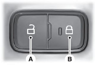
Locking and Unlocking the Doors from Inside

Locking the Doors
Press the lock switch on the door interior trim panel. The doors can no longer be released using the exterior door handle switches and the luggage compartment locks.
