Lincoln Aviator: Generator and Regulator / Removal and Installation - Generator - 3.0L EcoBoost
Removal
NOTE: Removal steps in this procedure may contain installation details.
-
Disconnect the battery.
Refer to: Battery Disconnect and Connect (414-01 Battery, Mounting and Cables, General Procedures).
-
Remove the air cleaner.
Refer to: Air Cleaner (303-12 Intake Air Distribution and Filtering - 3.0L EcoBoost/3.0L EcoBoost – Hybrid (BQ), Removal and Installation).
-
Detach the wire harness retainer from the CAC intake pipe and loosen the clamp at the LH turbocharger.
Torque: 48 lb.in (5.4 Nm)
.jpg) |
-
Release the clamp and disconnect the hose and the electrical connector from the CAC intake pipe. Detach the coolant hose retainers from the air cleaner bracket.
.jpg) |
-
-
Loosen the CAC intake pipe clamp.
Torque: 48 lb.in (5.4 Nm)
-
Remove the bolt.
Torque: 106 lb.in (12 Nm)
-
Loosen the CAC intake pipe clamp.
.jpg) |
-
Remove the 3 bolts and the air cleaner bracket.
Torque: 89 lb.in (10 Nm)
.jpg) |
-
NOTICE: The turbocharger compressor vanes can be damaged by even the smallest particles. When removing any turbocharger or engine air intake system component, ensure that no debris enters the system. Failure to do so may result in damage to the turbocharger.
Separate both ends of the CAC intake pipe and remove the CAC intake pipe.
.jpg) |
-
NOTICE: After installation, make sure the accessory drive belt is correctly seated on all the pulleys, if the belt is not properly seated on all of the pulleys component damage will occur.
-
Rotate the accessory drive belt tensioner clockwise.
-
Position the accessory drive belt aside.
-
Rotate the accessory drive belt tensioner clockwise.
.jpg) |
-
If equipped, remove the pin-type retainers, separate the clips and remove the LH hood air deflector.
.jpg) |
-
-
Depress the raised area of the air cleaner inlet pipe.
-
Remove the air cleaner inlet pipe.
-
Depress the raised area of the air cleaner inlet pipe.
.jpg) |
-
-
Remove the generator bolt.
Torque: 35 lb.ft (47.5 Nm)
-
Remove the generator nut.
Torque: 35 lb.ft (47.5 Nm)
-
Remove the generator stud.
Torque: 71 lb.in (8 Nm)
-
Position the generator with the pulley side down.
-
Remove the generator bolt.
.jpg) |
-
NOTICE: When installing the B+ terminal nut to the generator, finger-start the nut before tightening or component damage may occur.
NOTE: Use a long socket extension and wobble socket to access the B+ terminal nut between the water pump outlet tubes and the engine front cover.
-
Position the generator B+ wire terminal protective cover aside.
-
Remove the nut and position the generator B+ wire aside.
Torque: 155 lb.in (17.5 Nm)
-
Disconnect the generator electrical connector.
-
Detach the wire harness retainer and remove the generator.
-
Position the generator B+ wire terminal protective cover aside.
.jpg) |
Installation
-
To install, reverse the removal procedure.
-
Do not tighten the generator nut until the generator bolt is installed.
 Specifications
General Specifications
Item
Specification
Base and Reserve without trailer tow vehicles
Rating
220 amps
Generator amps at 80...
 Removal and Installation - Generator Pulley
Removal
WARNING:
Before beginning any service procedure in this
section, refer to Safety Warnings in section 100-00 General Information...
Other information:
Lincoln Aviator 2020-2026 Owners Manual: Cruise Control Module
Argentina Brazil Djibouti Ghana Indonesia Jamaica Malaysia RALM/61A/0318/S(18-0852) Mauritania Moldova Morocco Pakistan Paraguay Serbia Singapore South Africa South Korea R-CMM-DLH-L2C0065TR Syria Taiwan, China Ukraine United Arab Emirates United States and Canada WARNING: Changes or modifications not expressively approved by the party responsible for compliance could void the user's authority to operate the equipment...
Lincoln Aviator 2020-2026 Service Manual: Removal and Installation - Rear Heater Core
Special Tool(s) / General Equipment Hose Clamp Remover/Installer Removal NOTE: Removal steps in this procedure may contain installation details. Drain the cooling system. Refer to: Engine Cooling System Draining, Vacuum Filling and Bleeding (303-03A Engine Cooling - 3...
Categories
- Manuals Home
- Lincoln Aviator Owners Manual
- Lincoln Aviator Service Manual
- Changing the Front Wiper Blades - Vehicles With: Heated Wiper Blades
- Child Safety Locks
- Opening and Closing the Hood
- New on site
- Most important about car
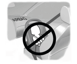
Children and Airbags
WARNING: Airbags can kill or injure a child in a child restraint. Never place a rear-facing child restraint in front of an active airbag. If you must use a forward-facing child restraint in the front seat, move the seat upon which the child restraint is installed all the way back.

