Lincoln Aviator 2020-2025 Service Manual / Chassis / Steering System / Steering Column / Removal and Installation - Steering Column Tilt Motor

Lincoln Aviator: Steering Column / Removal and Installation - Steering Column Tilt Motor

Removal

NOTE: Removal steps in this procedure may contain installation details.

  1. Remove the steering column.
    Refer to: Steering Column (211-04 Steering Column, Removal and Installation).
  1. NOTE: Note the position of the component before removal.


    Remove the tilt motor.
    1. Remove the trunnion bracket retainers and bracket.
    1. Remove the tilt motor retainers and remove the tilt motor.

Installation

  1. On both sides.
    Apply grease (supplied with the new motor) to the trunnion nut axles and the tilt motor lead-screw housing holes.
  1. Rotate the trunnion nut until the correct length is achieved to align the lead-screw housing with the threaded holes in the support arm.

  1. Install the tilt motor.
    1. Position the tilt motor and install the tilt motor retainers.
      Torque: 124 lb.in (14 Nm)
    1. Install the trunnion bracket and the trunnion bracket retainers.
      Torque: 71 lb.in (8 Nm)
  1. Install the steering column.
    Refer to: Steering Column (211-04 Steering Column, Removal and Installation).
  1. If equipped with memory steering column, use the steering column control switch and set the tilt motor soft stops as follows.
    1. Move the column upward until it reaches the end of travel.
    1. Move the column in the same direction until it reaches the end of travel again.
    1. Move the column downward until it reaches the end of travel.
    1. Move the column in the same direction until it reaches the end of travel again.

    Removal and Installation - Steering Column Telescopic Motor

    Removal NOTE: Removal steps in this procedure may contain installation details. Remove the steering column. Refer to: Steering Column (211-04 Steering Column, Removal and Installation)...

    Removal and Installation - Steering Column Upper Shaft

    Removal NOTE: Removal steps in this procedure may contain installation details. Remove the steering column. Refer to: Steering Column (211-04 Steering Column, Removal and Installation)...

    Other information:

    Lincoln Aviator 2020-2025 Service Manual: Diagnosis and Testing - Vehicle Dynamic Suspension


    Diagnostic Trouble Code (DTC) Chart Diagnostics in this manual assume a certain skill level and knowledge of Ford-specific diagnostic practices. REFER to: Diagnostic Methods (100-00 General Information, Description and Operation).   Diagnostic Trouble Code Chart Module   DTC Description Action   VDM C110C:11 Left Front Damper Solenoid: Circuit Short to Ground   GO to Pinpoint Test D   VDM C110C:12 Left Front Damper Solenoid: Circuit Short to Battery   GO to Pinpoint Test D   VDM C110C:13 Left Front Damper Solenoid: Circuit Open   GO to Pinpoint Test D   VDM C110C:64 Left Front Damper Solenoid:Signal Plausibility Failure   GO to Pinpoint Test D   VDM C110D:11 Right Front Damper Solenoid: Circuit Short to Ground   GO to Pinpoint Test E   VDM C110D:12 Right Front Damper Solenoid: Circuit Short to Battery   GO to Pinpoint Test E   VDM C110D:13 Right Front Damper Solenoid: Circuit Open   GO to Pinpoint Test E   VDM C110D:64 Right Front Damper Solenoid:Signal Plausibility Failure   GO to Pinpoint Test E   VDM C110E:11 Left Rear Damper Solenoid: Circuit Short to Ground   GO to Pinpoint Test F   VDM C110E:12 Left Rear Damper Solenoid: Circuit Short to Battery   GO to Pinpoint Test F   VDM C110E:13 Left Rear Damper Solenoid: Circuit Open   GO to Pinpoint Test F   VDM C110E:64 Left Rear Damper Solenoid:Signal Plausibility Failure   GO to Pinpoint Test F   VDM C110F:11 Right Rear Damper Solenoid: Circuit Short to Ground   GO to Pinpoint Test G   VDM C110F:12 Right Rear Damper Solenoid: Circuit Short to Battery   GO to Pinpoint Test G   VDM C110F:13 Right Rear Damper Solenoid: Circuit Open   GO to Pinpoint Test G   VDM C110F:64 Right Rear Damper Solenoid:Signal Plausibility Failure   GO to Pinpoint Test G   VDM C1124:55 Height Sensor(s):Not Configured   GO to Pinpoint Test U   VDM C1124:56 Height Sensor(s):Invalid/Incompatible Configuration   GO to Pinpoint Test U   VDM C1A03:11 Left Front Height Sensor: Circuit Short to Ground   GO to Pinpoint Test H   VDM C1A03:12 Left Front Height Sensor: Circuit Short to Battery   GO to Pinpoint Test H   VDM C1A03:29 Left Front Height Sensor:Signal Invalid   GO to Pinpoint Test H   VDM C1A03:64 Left Front Height Sensor:Signal Plausibility Failure   GO to Pinpoint Test T   VDM C1A04:11 Right Front Height Sensor: Circuit Short to Ground   GO to Pinpoint Test I   VDM C1A04:12 Right Front Height Sensor: Circuit Short to Battery   GO to Pinpoint Test I   VDM C1A04:29 Right Front Height Sensor:Signal Invalid   GO to Pinpoint Test I   VDM C1A04:64 Right Front Height Sensor:Signal Plausibility Failure   GO to Pinpoint Test T   VDM C1A05:11 Left Rear Height Sensor: Circuit Short to Ground   GO to Pinpoint Test J   VDM C1A05:12 Left Rear Height Sensor: Circuit Short to Battery   GO to Pinpoint Test J   VDM C1A05:29 Left Rear Height Sensor:Signal Invalid   GO to Pinpoint Test J   VDM C1A05:64 Left Rear Height Sensor:Signal Plausibility Failure   GO to Pinpoint Test T   VDM C1A06:11 Right Rear Height Sensor: Circuit Short to Ground   GO to Pinpoint Test K   VDM C1A06:12 Right Rear Height Sensor: Circuit Short to Battery   GO to Pinpoint Test K   VDM C1A06:29 Right Rear Height Sensor:Signal Invalid   GO to Pinpoint Test K   VDM C1A06:64 Right Rear Height Sensor:Signal Plausibility Failure   GO to Pinpoint Test T   VDM P1758:19 Pressure Solenoid Control System Incorrect Current: Circuit Current Above Threshold   GO to Pinpoint Test C   VDM U0100:87 Lost Communication With ECM / PCM: Missing Message   GO to Pinpoint Test M   VDM U0121:87 Lost Communication With Anti-Lock Brake System (ABS) Control Module: Missing Message   GO to Pinpoint Test N   VDM U0131:87 Lost Communication With EPAS module: Missing Message   GO to Pinpoint Test O   VDM U0140:87 Lost Communication With Body Control Module: Missing Message   GO to Pinpoint Test P   VDM U0151:87 Lost Communication With Restraints Control Module: Missing Message   GO to Pinpoint Test Q   VDM U0164:87 Lost Communication With HVAC Control Module:Missing Message   GO to Pinpoint Test R   VDM U023A:87 Lost Communication With Image Processing Module A:Missing Message   GO to Pinpoint Test S   VDM U0401:00 Invalid Data Received from ECM/PCM A:No Sub Type Information   GO to Pinpoint Test W   VDM U0415:00 Invalid Data Received from Anti-Lock Brake System (ABS) Control Module "A":No Sub Type Information   GO to Pinpoint Test X   VDM U0420:00 Invalid Data Received from Power Steering Control Module "A":No Sub Type Information   GO to Pinpoint Test Y   VDM U0422:00 Invalid Data Received From Body Control Module:No Sub Type Information   GO to Pinpoint Test Z   VDM U0424:00 Invalid Data Received From HVAC Control Module:No Sub Type Information   GO to Pinpoint Test AA   VDM U0452:00 Invalid Data Received From Restraints Control Module:No Sub Type Information   GO to Pinpoint Test AB   VDM U053B:00 Invalid Data Received From Image Processing Module A:No Sub Type Information   GO to Pinpoint Test AC   VDM U1000:00 Solid State Driver Protection Active -Driver Disabled:No Sub Type Information   GO to Pinpoint Test V   VDM U200D:11 Control Module Output Power A: Circuit Short to Ground   GO to Pinpoint Test L   VDM U200D:12 Control Module Output Power A: Circuit Short to Battery   GO to Pinpoint Test L   VDM U200E:11 Control Module Output Power B: Circuit Short to Ground   GO to Pinpoint Test L   VDM U200E:12 Control Module Output Power B: Circuit Short to Battery   GO to Pinpoint Test L   VDM U200F:11 Control Module Output Power C:Circuit Short To Ground   GO to Pinpoint Test J   VDM U200F:12 Control Module Output Power C:Circuit Short To Battery   GO to Pinpoint Test J   VDM U201E:11 Control Module Output Power D:Circuit Short To Ground   GO to Pinpoint Test K   VDM U201E:12 Control Module Output Power D:Circuit Short To Battery   GO to Pinpoint Test K   VDM U2024:51 Control Module Cal-Config Data:Not Programmed   GO to Pinpoint Test V   VDM U2100:00 Initial Configuration Not Complete:No Sub Type Information   GO to Pinpoint Test V   VDM U2200:00 Control Module Configuration Memory Corrupt:No Sub Type Information   GO to Pinpoint Test V   VDM U3000:04 Control Module:System Internal Failures   GO to Pinpoint Test V   VDM U3000:49 Control Module:Internal Electronic Failure   GO to Pinpoint Test V   VDM U3003:16 Battery Voltage: Circuit Voltage Below Threshold   GO to Pinpoint Test A   VDM U3003:17 Battery Voltage: Circuit Voltage Above Threshold   GO to Pinpoint Test B Symptom Chart Symptom Chart: Vehicle Dynamic Suspension Diagnostics in this manual assume a certain skill level and knowledge of Ford-specific diagnostic practices...

    Lincoln Aviator 2020-2025 Service Manual: Removal and Installation - High Voltage Battery Cables - Plug-In Hybrid Electric Vehicle (PHEV)


    Removal   WARNING: To prevent the risk of high-voltage shock, always follow precisely all warnings and service instructions, including instructions to depower the system. The high-voltage system utilizes approximately 450 volts DC, provided through high-voltage cables to its components and modules...

    Categories

    Child Seats

    Lincoln Aviator. Child Seats

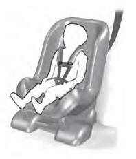
    Use a child restraint (sometimes called an infant carrier, convertible seat, or toddler seat) for infants, toddlers and children weighing 40 lb (18 kg) or less (generally four-years-old or younger).

    Using Lap and Shoulder Belts

    WARNING: Do not place a rearward facing child restraint in front of an active airbag. Failure to follow this instruction could result in personal injury or death.

    read more

     
    Copyright © 2025 www.liaviator2.com