Lincoln Aviator: Steering System / Steering Column
- Description and Operation - Steering Column - System Operation and Component Description
- Diagnosis and Testing - Steering Column
- General Procedures - Steering Wheel Cover Repair
- Removal and Installation - Steering Column
- Removal and Installation - Steering Column Lower Shaft
- Removal and Installation - Steering Column Opening Seal
- Removal and Installation - Steering Column Telescopic Motor
- Removal and Installation - Steering Column Tilt Motor
- Removal and Installation - Steering Column Upper Shaft
- Removal and Installation - Steering Wheel
- Removal and Installation - Steering Wheel - Vehicles With: Adaptive Steering
 Removal and Installation - Tie Rod End
Special Tool(s) /
General Equipment
Tie Rod End Remover
Removal
NOTE:
Removal steps in this procedure may contain installation details.
Remove the wheel and tire...
 Description and Operation - Steering Column - System Operation and Component Description
System Diagram
Item
Description
1
DDM
2
SCCM
3
Memory set switch
4
DSM
5
BCM
6
MS-CAN
7
HS-CAN2
8
Steering column control switch
9
Steering column tilt motor
10
Hall effect sensor
11
GWM
12
Steering column telescopic motor
13
Hall effect sensor
14
HS-CAN1
System Operation
Network Message Chart - Power Adjustable Steering Column
Module Network Input Messages
Broadcast Message
Originating Module
Message Purpose
Ignition status
BCM
Communicates the ignition status to initiate the easy entry and exit feature...
Other information:
Lincoln Aviator 2020-2026 Service Manual: Removal and Installation - Turbine Shaft Speed (TSS) Sensor
Removal Remove the main control valve body. Refer to: Main Control Valve Body (307-01A Automatic Transmission - 10-Speed Automatic Transmission – 10R60, Removal and Installation). Remove the TSS sensor. Slide the plastic lock to the unlocked position...
Lincoln Aviator 2020-2026 Service Manual: General Procedures - Corrosion Prevention
Special Tool(s) / General Equipment Rust Protection Coating Gun Undercoating Gun Materials Name Specification ValuGard™ Premium UndercoatingVG101, VG101A - ValuGard™ Rust InhibitorVG104, VG104A - Motorcraft® Metal Surface Prep WipesZC-31-B - Repair NOTE: Undercoating NOTE: The following illustrations are not vehicle specific and are intended for reference only...
Categories
- Manuals Home
- Lincoln Aviator Owners Manual
- Lincoln Aviator Service Manual
- Opening and Closing the Hood
- Keyless Entry
- Remove and Reinstall the Battery
- New on site
- Most important about car
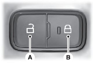
Locking and Unlocking the Doors from Inside

Locking the Doors
Press the lock switch on the door interior trim panel. The doors can no longer be released using the exterior door handle switches and the luggage compartment locks.
Copyright © 2026 www.liaviator2.com
