Lincoln Aviator: Power Steering / Removal and Installation - Tie Rod End
Special Tool(s) / General Equipment
| Tie Rod End Remover |
Removal
NOTE: Removal steps in this procedure may contain installation details.
-
Remove the wheel and tire.
Refer to: Wheel and Tire (204-04A Wheels and Tires, Removal and Installation).
-
-
Loosen the tie rod end jam nut.
Torque: 35 lb.ft (48 Nm)
-
Remove and discard the outer tie rod end nut.
Torque: 52 lb.ft (70 Nm)
-
NOTICE: Do not use a hammer to separate the outer tie-rod end from the wheel spindle or damage to the wheel spindle may result.
NOTICE: Use care when installing the tie rod separator or damage to the outer tie-rod end boot may occur.
Separate the outer tie rod end from the wheel knuckle.
Use the General Equipment: Tie Rod End Remover
-
Loosen the tie rod end jam nut.
.jpg) |
-
NOTE: Count and record the number of turns required to remove the outer tie-rod end for reference during installation.
Remove the tie-rod end.
.jpg) |
Installation
-
To install, reverse the removal procedure.
-
Check and if necessary, adjust front toe.
Refer to: Front Toe Adjustment (204-00 Suspension System - General Information, General Procedures).
 Removal and Installation - Tie Rod
Special Tool(s) /
General Equipment
Boot Clamp Pliers
Materials
Name
Specification
Motorcraft® Premium Long-Life GreaseXG-1-E1
ESA-M1C75-B
Removal
NOTICE:
When servicing inner tie rods, install a new bellows boot
and clamps...
Other information:
Lincoln Aviator 2020-2026 Service Manual: Removal and Installation - Selector Shaft Seal
Special Tool(s) / General Equipment 307-549Installer, Shift Shaft Fluid SealTKIT-2005D1-F1 Materials Name Specification Motorcraft® MERCON® ULV Automatic Transmission FluidXT-12-QULV WSS-M2C949-A, MERCON® ULV Removal With the vehicle in NEUTRAL, position it on a hoist...
Lincoln Aviator 2020-2026 Service Manual: Removal and Installation - Front Seat Track
Removal NOTE: Removal steps in this procedure may contain installation details. Remove the front seat backrest. Refer to: Front Seat Backrest (501-10A Front Seats, Removal and Installation). Remove the front seatbelt buckle...
Categories
- Manuals Home
- Lincoln Aviator Owners Manual
- Lincoln Aviator Service Manual
- Drive Modes
- Remove and Reinstall the Battery
- Changing the Front Wiper Blades - Vehicles With: Heated Wiper Blades
- New on site
- Most important about car
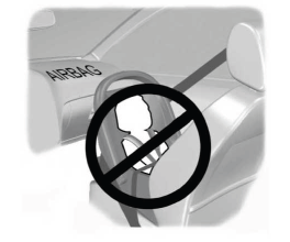
Children and Airbags
WARNING: Airbags can kill or injure a child in a child restraint. Never place a rear-facing child restraint in front of an active airbag. If you must use a forward-facing child restraint in the front seat, move the seat upon which the child restraint is installed all the way back.


