Lincoln Aviator 2020-2026 Service Manual / Body and Paint / Body and Paint / Wipers and Washers / Removal and Installation - Windshield Wiper Blade Insert
Lincoln Aviator: Wipers and Washers / Removal and Installation - Windshield Wiper Blade Insert
Special Tool(s) / General Equipment
| Flat Headed Screw Driver |
Removal
NOTE: Left hand side (LH) shown, right hand side (RH) similar.
-
Lift the windshield wiper blade and arm assembly off of the windshield.
.jpg) |
-
Rotate the blade towards the windshield until the blade is locked in position.
.jpg) |
-
Remove the windshield wiper blade assembly.
-
Press the release tab.
-
Remove the windshield wiper blade assembly from the windshield wiper pivot arm.
-
Press the release tab.
.jpg) |
-
NOTICE: To prevent windshield damage, lower the wiper arm during the repair.
Carefully lower the windshield wiper arm assembly onto the windshield.
.jpg) |
-
Remove the windshield wiper blade insert.
-
Press the end cap locking tab.
Use the General Equipment: Flat Headed Screw Driver
-
Remove the windshield wiper blade insert.
-
Press the end cap locking tab.
.jpg) |
Installation
-
NOTE: Make sure the windshield wiper blade insert is aligned properly with the windshield wiper blade assembly channel.
Install the windshield wiper blade insert.
.jpg) |
-
-
Push the end cap in until it locks into position.
-
Make sure the windshield wiper blade insert is fully seated into the end cap.
-
Push the end cap in until it locks into position.
.jpg) |
-
Lift the windshield wiper arm assembly off of the windshield.
.jpg) |
-
Install the windshield wiper blade assembly.
-
Line up blade water and electrical connectors with
the receptacles on the arm by lifting arm from the windshield.
-
Push the windshield wiper blade assembly in until it locks into place.
-
NOTE: Make sure the windshield wiper blade assembly pivots freely.
Push the windshield wiper blade assembly upwards until it locks into place.
-
Line up blade water and electrical connectors with
the receptacles on the arm by lifting arm from the windshield.
.jpg) |
-
Lower the windshield wiper blade and arm assembly onto the windshield.
.jpg) |
 Removal and Installation - Windshield Washer Reservoir
Special Tool(s) /
General Equipment
Fluid Suction Gun
Fluid Container
Materials
Name
Specification
Motorcraft® Premium Windshield Wash Concentrate with BitterantZC-32-B2
WSS-M14P19-A
Removal
NOTE:
Removal steps in this procedure may contain installation details...
 Removal and Installation - Windshield Wiper Motor
Removal
NOTE:
Removal steps in this procedure may contain installation details.
Remove the wiper linkage assembly.
Refer to: Wiper Linkage Assembly (501-16 Wipers and Washers, Removal and Installation)...
Other information:
Lincoln Aviator 2020-2026 Service Manual: Disassembly and Assembly - Driveshaft Center Bearing
Special Tool(s) / General Equipment Hydraulic Press Bearing Separator Materials Name Specification Motorcraft® Premium Long-Life GreaseXG-1-E1 ESA-M1C75-B DISASSEMBLY Remove the rear driveshaft slip yoke boot...
Lincoln Aviator 2020-2026 Service Manual: Removal and Installation - Heating, Ventilation and Air Conditioning (HVAC) Control Module
Removal NOTE: Removal steps in this procedure may contain installation details. NOTE: If installing a new module, it is necessary to upload the module configuration information to the scan tool prior to removing the module. This information must be downloaded into the new module after installation...
Categories
- Manuals Home
- Lincoln Aviator Owners Manual
- Lincoln Aviator Service Manual
- Changing the Front Wiper Blades - Vehicles With: Heated Wiper Blades
- Configuring The Head Up Display
- USB Port and Power Point Locations
- New on site
- Most important about car
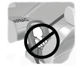
Children and Airbags
WARNING: Airbags can kill or injure a child in a child restraint. Never place a rear-facing child restraint in front of an active airbag. If you must use a forward-facing child restraint in the front seat, move the seat upon which the child restraint is installed all the way back.

Copyright © 2026 www.liaviator2.com
