Lincoln Aviator: Navigation (If Equipped) / Route Guidance

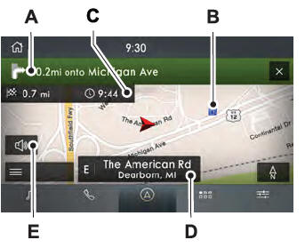
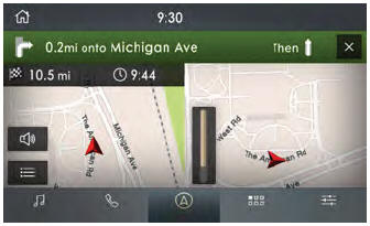
- Turn indicator. Select to hear the
last voice prompt.
- Point of interest.
- Estimated time of arrival, distance
to destination or time to
destination.
- Current road.
- Mute guidance prompts.
Note: To change guidance prompt volume,
turn the volume control when a guidance
prompt plays.
Route Guidance Menu

Adjusting the Guidance Prompt Volume
Turn the volume control when a guidance
prompt plays to adjust the volume.
Note: If you have inadvertently adjusted the
volume to zero, press the turn indicator
button to play the last voice prompt and then
adjust the volume to the desired level.
Muting Guidance Prompts
Select the mute option on the
screen to mute guidance prompts.
Note: The system mutes the next and all
future guidance prompts.
Adding Waypoints
You can add a waypoint to a navigation route
as a destination along your route. You can
add up to five waypoints.
- Select the search option on the map.
- Set a destination.
- Select Add Waypoint.
- Select Go.
Canceling Route Guidance
Select the route guidance menu
option on the active guidance
screen.
Select Cancel Route.

Note: The route guidance menu option is
always in the bottom right-hand corner of
the main map.
cityseeker (If Equipped)
Note: cityseeker point of interest (POI)
information is limited to approximately 1,110
cities (1,049 in the United States, 36 in
Canada and 15 in Mexico).

cityseeker, when available, is a service that
provides more information about certain
points of interest such as restaurants, hotels
and attractions.
When you have selected a point of interest,
the location and information appear, such as
address, phone number and a star rating.
Press More Information to see a photo, a
review, a list of services and facilities, the
average room or meal price and the web
address. This screen displays the point of
interest icons.
For restaurants, cityseeker can provide
information such as star rating, average cost,
review, handicap access, hours of operation,
and website address.
For hotels, cityseeker can provide
information such as star rating, price
category, review, check-in and checkout
times, hotel service icons and website
address. Hotel service icons include:
- Restaurant
- Business center
- Handicap facilities
- Laundry
- Refrigerator
- 24 hour room service
- Fitness center
- Internet access
- Pool
- Wi-Fi
Attractions include nearby landmarks,
amusement parks, historic buildings and
more. cityseeker can provide information
such as star rating, reviews, hour of operation
and admission price.
Display more or less detail on the map.
Note: You can use pinch gestures to zoom
in and out. Place two fingers on the screen
and move them apart to zoom in...
SiriusXM Traffic and Travel Link is available
on vehicles equipped with navigation and
only in select markets. You must activate and
subscribe to receive SiriusXM Traffic and
Travel Link information...
Other information:
Diagnostic Trouble Code (DTC) Chart
Diagnostics in this manual assume a certain skill level and knowledge of Ford-specific diagnostic practices. REFER to: Diagnostic Methods (100-00 General Information, Description and Operation).
Diagnostic Trouble Code Chart
Module
DTC
Description
Action
VDM
C110C:11
Left Front Damper Solenoid: Circuit Short to Ground
GO to Pinpoint Test D
VDM
C110C:12
Left Front Damper Solenoid: Circuit Short to Battery
GO to Pinpoint Test D
VDM
C110C:13
Left Front Damper Solenoid: Circuit Open
GO to Pinpoint Test D
VDM
C110C:64
Left Front Damper Solenoid:Signal Plausibility Failure
GO to Pinpoint Test D
VDM
C110D:11
Right Front Damper Solenoid: Circuit Short to Ground
GO to Pinpoint Test E
VDM
C110D:12
Right Front Damper Solenoid: Circuit Short to Battery
GO to Pinpoint Test E
VDM
C110D:13
Right Front Damper Solenoid: Circuit Open
GO to Pinpoint Test E
VDM
C110D:64
Right Front Damper Solenoid:Signal Plausibility Failure
GO to Pinpoint Test E
VDM
C110E:11
Left Rear Damper Solenoid: Circuit Short to Ground
GO to Pinpoint Test F
VDM
C110E:12
Left Rear Damper Solenoid: Circuit Short to Battery
GO to Pinpoint Test F
VDM
C110E:13
Left Rear Damper Solenoid: Circuit Open
GO to Pinpoint Test F
VDM
C110E:64
Left Rear Damper Solenoid:Signal Plausibility Failure
GO to Pinpoint Test F
VDM
C110F:11
Right Rear Damper Solenoid: Circuit Short to Ground
GO to Pinpoint Test G
VDM
C110F:12
Right Rear Damper Solenoid: Circuit Short to Battery
GO to Pinpoint Test G
VDM
C110F:13
Right Rear Damper Solenoid: Circuit Open
GO to Pinpoint Test G
VDM
C110F:64
Right Rear Damper Solenoid:Signal Plausibility Failure
GO to Pinpoint Test G
VDM
C1124:55
Height Sensor(s):Not Configured
GO to Pinpoint Test U
VDM
C1124:56
Height Sensor(s):Invalid/Incompatible Configuration
GO to Pinpoint Test U
VDM
C1A03:11
Left Front Height Sensor: Circuit Short to Ground
GO to Pinpoint Test H
VDM
C1A03:12
Left Front Height Sensor: Circuit Short to Battery
GO to Pinpoint Test H
VDM
C1A03:29
Left Front Height Sensor:Signal Invalid
GO to Pinpoint Test H
VDM
C1A03:64
Left Front Height Sensor:Signal Plausibility Failure
GO to Pinpoint Test T
VDM
C1A04:11
Right Front Height Sensor: Circuit Short to Ground
GO to Pinpoint Test I
VDM
C1A04:12
Right Front Height Sensor: Circuit Short to Battery
GO to Pinpoint Test I
VDM
C1A04:29
Right Front Height Sensor:Signal Invalid
GO to Pinpoint Test I
VDM
C1A04:64
Right Front Height Sensor:Signal Plausibility Failure
GO to Pinpoint Test T
VDM
C1A05:11
Left Rear Height Sensor: Circuit Short to Ground
GO to Pinpoint Test J
VDM
C1A05:12
Left Rear Height Sensor: Circuit Short to Battery
GO to Pinpoint Test J
VDM
C1A05:29
Left Rear Height Sensor:Signal Invalid
GO to Pinpoint Test J
VDM
C1A05:64
Left Rear Height Sensor:Signal Plausibility Failure
GO to Pinpoint Test T
VDM
C1A06:11
Right Rear Height Sensor: Circuit Short to Ground
GO to Pinpoint Test K
VDM
C1A06:12
Right Rear Height Sensor: Circuit Short to Battery
GO to Pinpoint Test K
VDM
C1A06:29
Right Rear Height Sensor:Signal Invalid
GO to Pinpoint Test K
VDM
C1A06:64
Right Rear Height Sensor:Signal Plausibility Failure
GO to Pinpoint Test T
VDM
P1758:19
Pressure Solenoid Control System Incorrect Current: Circuit Current Above Threshold
GO to Pinpoint Test C
VDM
U0100:87
Lost Communication With ECM / PCM: Missing Message
GO to Pinpoint Test M
VDM
U0121:87
Lost Communication With Anti-Lock Brake System (ABS) Control Module: Missing Message
GO to Pinpoint Test N
VDM
U0131:87
Lost Communication With EPAS module: Missing Message
GO to Pinpoint Test O
VDM
U0140:87
Lost Communication With Body Control Module: Missing Message
GO to Pinpoint Test P
VDM
U0151:87
Lost Communication With Restraints Control Module: Missing Message
GO to Pinpoint Test Q
VDM
U0164:87
Lost Communication With HVAC Control Module:Missing Message
GO to Pinpoint Test R
VDM
U023A:87
Lost Communication With Image Processing Module A:Missing Message
GO to Pinpoint Test S
VDM
U0401:00
Invalid Data Received from ECM/PCM A:No Sub Type Information
GO to Pinpoint Test W
VDM
U0415:00
Invalid Data Received from Anti-Lock Brake System (ABS) Control Module "A":No Sub Type Information
GO to Pinpoint Test X
VDM
U0420:00
Invalid Data Received from Power Steering Control Module "A":No Sub Type Information
GO to Pinpoint Test Y
VDM
U0422:00
Invalid Data Received From Body Control Module:No Sub Type Information
GO to Pinpoint Test Z
VDM
U0424:00
Invalid Data Received From HVAC Control Module:No Sub Type Information
GO to Pinpoint Test AA
VDM
U0452:00
Invalid Data Received From Restraints Control Module:No Sub Type Information
GO to Pinpoint Test AB
VDM
U053B:00
Invalid Data Received From Image Processing Module A:No Sub Type Information
GO to Pinpoint Test AC
VDM
U1000:00
Solid State Driver Protection Active -Driver Disabled:No Sub Type Information
GO to Pinpoint Test V
VDM
U200D:11
Control Module Output Power A: Circuit Short to Ground
GO to Pinpoint Test L
VDM
U200D:12
Control Module Output Power A: Circuit Short to Battery
GO to Pinpoint Test L
VDM
U200E:11
Control Module Output Power B: Circuit Short to Ground
GO to Pinpoint Test L
VDM
U200E:12
Control Module Output Power B: Circuit Short to Battery
GO to Pinpoint Test L
VDM
U200F:11
Control Module Output Power C:Circuit Short To Ground
GO to Pinpoint Test J
VDM
U200F:12
Control Module Output Power C:Circuit Short To Battery
GO to Pinpoint Test J
VDM
U201E:11
Control Module Output Power D:Circuit Short To Ground
GO to Pinpoint Test K
VDM
U201E:12
Control Module Output Power D:Circuit Short To Battery
GO to Pinpoint Test K
VDM
U2024:51
Control Module Cal-Config Data:Not Programmed
GO to Pinpoint Test V
VDM
U2100:00
Initial Configuration Not Complete:No Sub Type Information
GO to Pinpoint Test V
VDM
U2200:00
Control Module Configuration Memory Corrupt:No Sub Type Information
GO to Pinpoint Test V
VDM
U3000:04
Control Module:System Internal Failures
GO to Pinpoint Test V
VDM
U3000:49
Control Module:Internal Electronic Failure
GO to Pinpoint Test V
VDM
U3003:16
Battery Voltage: Circuit Voltage Below Threshold
GO to Pinpoint Test A
VDM
U3003:17
Battery Voltage: Circuit Voltage Above Threshold
GO to Pinpoint Test B
Symptom Chart
Symptom Chart: Vehicle Dynamic Suspension
Diagnostics
in this manual assume a certain skill level and knowledge of
Ford-specific diagnostic practices...
Removal
NOTE:
Removal steps in this procedure may contain installation details.
Remove the front door trim panel.
Refer to: Front Door Trim Panel (501-05 Interior Trim and Ornamentation, Removal and Installation).
Remove the screws and the front door tweeter speaker...