Lincoln Aviator: Adaptive Cruise Control / Setting the Adaptive Cruise Control Gap
 Press the button to cycle through
the four gap settings.
Press the button to cycle through
the four gap settings.

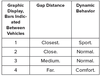
The selected gap appears in the instrument cluster display as shown by the bars in the image.
Note: The gap setting is time dependent and therefore, the distance adjusts with your vehicle speed.
Note: It is your responsibility to select a gap appropriate to the driving conditions.
Adaptive Cruise Control Gap Settings
Each time you switch the system on, it selects the last chosen gap setting.
Following a Vehicle
When a vehicle ahead of you enters the same lane or a slower vehicle is ahead in the same lane, the vehicle speed adjusts to maintain the gap setting.
Note: When you are following a vehicle and you switch on a turn signal lamp, adaptive cruise control may provide a small, temporary acceleration to help you pass.
Your vehicle maintains a consistent gap from the vehicle ahead until:
- The vehicle in front of you accelerates to a speed above the set speed.
- The vehicle in front of you moves out of the lane you are in.
- You set a new gap distance.
The system applies the brakes to slow down your vehicle to maintain a safe gap distance from the vehicle in front of you. The system only applies limited braking. You can override the system by applying the brakes.
Note: The brakes may emit noise when applied by the system.
If the system determines that its maximum braking level is not sufficient, an audible warning sounds, a message appears in the instrument cluster display and an indicator flashes when the system continues to brake. Take immediate action.
 Setting the Adaptive Cruise Control Speed
Drive to the speed you prefer.
Press either button to set the
current speed.
Take your foot off the accelerator pedal.
The indicator, current gap setting and set
speed appear in the information display...
 Canceling the Set Speed. Resuming the Set Speed
Canceling the Set Speed
Press the button or tap the
brake
pedal.
The set speed does not erase.
Resuming the Set Speed
Press the button.
Your vehicle speed returns to the previously
set speed and gap setting...
Other information:
Lincoln Aviator 2020-2026 Service Manual: Description and Operation - Front Seats - System Operation and Component Description
System Operation System Diagram - Driver Memory Seat Item Description 1 HS-CAN1 2 PCM 3 BCM 4 HS-CAN1 5 Ignition Switch 6 GWM 7 Memory Set Switch 8 MS-CAN 9 DSM 10 MS-CAN 11 DDM 12 Memory Power Seat Motors 13 LIN 14 Driver Seat Control Switch 15 SCMG 16 MS-CAN 17 With Multi-Contour Seats Network Message Chart - Driver Memory Seat DSM Network Input Messages Broadcast Message Originating Module Message Purpose Key-in-ignition status BCM Provides the ignition status...
Lincoln Aviator 2020-2026 Service Manual: Diagnosis and Testing - Cruise Control
Diagnostic Trouble Code (DTC) Chart Diagnostics in this manual assume a certain skill level and knowledge of Ford-specific diagnostic practices. REFER to: Diagnostic Methods (100-00 General Information, Description and Operation). Diagnostic Trouble Code Chart Module DTC Description Action PCM P0504:00 Brake Switch A / B Correlation: No Sub Type Information GO to Pinpoint Test B PCM P0572:00 Brake Switch "A" Circuit Low: No Sub Type Information GO to Pinpoint Test B PCM P0573:00 Brake Switch "A" Circuit High: No Sub Type Information GO to Pinpoint Test B PCM P1703:00 Brake Switch Out Of Self - Test Range: No Sub Type Information GO to Pinpoint Test B PCM P1935:00 Brake Switch/Sensor Signal: No Sub Type Information GO to Pinpoint Test B SIMA P0564:11 Cruise Control Multi-Function Input "A" Circuit: Circuit Short To Ground GO to Pinpoint Test A SIMA P0564:12 Cruise Control Mulit-Function Input "A" Circuit: Circuit Short To Battery GO to Pinpoint Test A SIMA P0564:13 Cruise Control Mulit-Function Input "A" Circuit: Circuit Open GO to Pinpoint Test A SIMA P0589:11 Cruise Control Multi-Function Input "B" Circuit: Circuit Short To Ground GO to Pinpoint Test A SIMA P0589:12 Cruise Control Mulit-Function Input "B" Circuit: Circuit Short To Battery GO to Pinpoint Test A SIMA P0589:13 Cruise Control Mulit-Function Input "B" Circuit: Circuit Open GO to Pinpoint Test A Global Customer Symptom Code (GCSC) Chart Diagnostics in this manual assume a certain skill level and knowledge of Ford-specific diagnostic practices...
Categories
- Manuals Home
- Lincoln Aviator Owners Manual
- Lincoln Aviator Service Manual
- Garage Door Opener
- Opening and Closing the Hood
- Drive Modes
- New on site
- Most important about car
Emergency Locking
Each door has a backup power system which allows the door to function if your vehicle has no power. The system has a limited number of operations before the power is depleted and turns off. When the system turns off, the door remains open and unlatched and does not close.
If your vehicle has no power and the backup power system is turned off, you can close and secure your vehicle by manually resetting each door latch using a key in the position shown.