Lincoln Aviator: Adaptive Cruise Control / Setting the Adaptive Cruise Control Speed
Drive to the speed you prefer.

 Press either button to set the
current speed.
Take your foot off the accelerator pedal.
The indicator, current gap setting and set speed appear in the information display.

A vehicle image illuminates if there is a vehicle detected in front of you.
Note: When adaptive cruise control is active, the speedometer may vary slightly from the set speed displayed in the information display.
Setting the Adaptive Cruise Speed from a Complete Stop

 Press and release either button
while keeping the brake pedal fully
pressed.
The set speed adjusts to 20 mph (30 km/h).
The indicator, current gap setting and set speed appear in the information display.
Manually Changing the Set Speed
 Press and release to increase the
set speed in small increments.
 Press and release to decrease the
set speed in small increments.
Press and hold either button to change the set speed in large increments. Release the button when you reach the speed you prefer.
Press the accelerator or brake pedal until you reach the speed you prefer. Press either button to select the current speed as the set speed.
The system may apply the brakes to slow the vehicle to the new set speed. The set speed displays continuously in the information display when the system is active.
 Switching Adaptive Cruise Control On and Off
The cruise controls are on the steering
wheel.
Switching Adaptive Cruise Control On
Press the button to set the
system
in standby mode.
The indicator, current gap setting and set
speed appear in the information display...
 Setting the Adaptive Cruise Control Gap
Press the button to cycle through
the four gap settings.
The selected gap appears in the instrument
cluster display as shown by the bars in the
image...
Other information:
Lincoln Aviator 2020-2026 Service Manual: Diagnosis and Testing - Vehicle Dynamic Suspension - Vehicles With: Air Suspension
Diagnostic Trouble Code (DTC) Chart Diagnostics in this manual assume a certain skill level and knowledge of Ford-specific diagnostic practices. REFER to: Diagnostic Methods (100-00 General Information, Description and Operation). Diagnostic Trouble Code Chart Module DTC Description Action SUMA B1041:52 Levelling Control: Not Activated GO to Pinpoint Test W SUMA C1043:00 Pressure Decrease Too Slow From Reservoir: No Sub Type Information GO to Pinpoint Test M SUMA C104C:11 Left Rear Spring Rate Valve: Circuit Short To Ground GO to Pinpoint Test E SUMA C104C:12 Left Rear Spring Rate Valve: Circuit Short To Battery GO to Pinpoint Test E SUMA C104C:13 Left Rear Spring Rate Valve: Circuit Open GO to Pinpoint Test E SUMA C104C:1A Left Rear Spring Rate Valve: Circuit Resistance Below Threshold GO to Pinpoint Test E SUMA C104C:1F Left Rear Spring Rate Valve: Circuit Intermittent GO to Pinpoint Test E SUMA C104D:11 Right Front Spring Rate Valve: Circuit Short To Ground GO to Pinpoint Test D SUMA C104D:12 Right Front Spring Rate Valve: Circuit Short To Battery GO to Pinpoint Test D SUMA C104D:13 Right Front Spring Rate Valve: Circuit Open GO to Pinpoint Test D SUMA C104D:1A Right Front Spring Rate Valve: Circuit Resistance Below Threshold GO to Pinpoint Test D SUMA C104D:1F Right Front Spring Rate Valve: Circuit Intermittent GO to Pinpoint Test D SUMA C104E:11 Right Rear Spring Rate Valve: Circuit Short To Ground GO to Pinpoint Test F SUMA C104E:12 Right Rear Spring Rate Valve: Circuit Short To Battery GO to Pinpoint Test F SUMA C104E:13 Right Rear Spring Rate Valve: Circuit Open GO to Pinpoint Test F SUMA C104E:1A Right Rear Spring Rate Valve: Circuit Resistance Below Threshold GO to Pinpoint Test F SUMA C104E:1F Right Rear Spring Rate Valve: Circuit Intermittent GO to Pinpoint Test F SUMA C104F:11 Left Front Spring Rate Valve: Circuit Short To Ground GO to Pinpoint Test C SUMA C104F:12 Left Front Spring Rate Valve: Circuit Short To Battery GO to Pinpoint Test C SUMA C104F:13 Left Front Spring Rate Valve: Circuit Open GO to Pinpoint Test C SUMA C104F:1A Left Front Spring Rate Valve: Circuit Resistance Below Threshold GO to Pinpoint Test C SUMA C104F:1F Left Front Spring Rate Valve: Circuit Intermittent GO to Pinpoint Test C SUMA C1124:07 Height Sensor(s): Mechanical Failures GO to Pinpoint Test G SUMA C1124:11 Height Sensor(s): Circuit Short To Ground GO to Pinpoint Test H SUMA C1124:12 Height Sensor(s): Circuit Short To Battery GO to Pinpoint Test H SUMA C1124:54 Height Sensor(s): Missing Calibration GO to Pinpoint Test U SUMA C1A03:2A Left Front Height Sensor: Stuck in Range GO to Pinpoint Test I SUMA C1A03:34 Left Front Height Sensor: Signal High Time Less Than Minimum GO to Pinpoint Test I SUMA C1A03:35 Left Front Height Sensor: Signal High Time Greater Than Maximum GO to Pinpoint Test I SUMA C1A03:36 Left Front Height Sensor: Signal Frequency Too Low GO to Pinpoint Test I SUMA C1A03:37 Left Front Height Sensor: Signal Frequency Too High GO to Pinpoint Test I SUMA C1A03:84 Left Front Height Sensor: Signal Below Allowable Range GO to Pinpoint Test I SUMA C1A03:85 Left Front Height Sensor: Signal Above Allowable Range GO to Pinpoint Test I SUMA C1A04:2A Right Front Height Sensor: Stuck in Range GO to Pinpoint Test J SUMA C1A04:34 Right Front Height Sensor: Signal High Time Less Than Minimum GO to Pinpoint Test J SUMA C1A04:35 Right Front Height Sensor: Signal High Time Greater Than Maximum GO to Pinpoint Test J SUMA C1A04:36 Right Front Height Sensor: Signal Frequency Too Low GO to Pinpoint Test J SUMA C1A04:37 Right Front Height Sensor: Signal Frequency Too High GO to Pinpoint Test J SUMA C1A04:84 Right Front Height Sensor: Signal Below Allowable Range GO to Pinpoint Test J SUMA C1A04:85 Right Front Height Sensor: Signal Above Allowable Range GO to Pinpoint Test J SUMA C1A05:2A Left Rear Height Sensor: Stuck in Range GO to Pinpoint Test K SUMA C1A05:34 Left Rear Height Sensor: Signal High Time Less Than Minimum GO to Pinpoint Test K SUMA C1A05:35 Left Rear Height Sensor: Signal High Time Greater Than Maximum GO to Pinpoint Test K SUMA C1A05:36 Left Rear Height Sensor: Signal Frequency Too Low GO to Pinpoint Test K SUMA C1A05:37 Left Rear Height Sensor: Signal Frequency Too High GO to Pinpoint Test K SUMA C1A05:84 Left Rear Height Sensor: Signal Below Allowable Range GO to Pinpoint Test K SUMA C1A05:85 Left Rear Height Sensor: Signal Above Allowable Range GO to Pinpoint Test K SUMA C1A06:2A Right Rear Height Sensor: Stuck in Range GO to Pinpoint Test L SUMA C1A06:34 Right Rear Height Sensor: Signal High Time Less Than Minimum GO to Pinpoint Test L SUMA C1A06:35 Right Rear Height Sensor: Signal High Time Greater Than Maximum GO to Pinpoint Test L SUMA C1A06:36 Right Rear Height Sensor: Signal Frequency Too Low GO to Pinpoint Test L SUMA C1A06:37 Right Rear Height Sensor: Signal Frequency Too High GO to Pinpoint Test L SUMA C1A06:84 Right Rear Height Sensor: Signal Below Allowable Range GO to Pinpoint Test L SUMA C1A06:85 Right Rear Height Sensor: Signal Above Allowable Range GO to Pinpoint Test L SUMA C1A20:00 Pressure Increase Too Slow When Filling Reservoir: No Sub Type Information GO to Pinpoint Test M SUMA C1A27:09 Compressor: Component Failures GO to Pinpoint Test N SUMA C1A27:63 Compressor: Circuit/Component Protection Time-Out GO to Pinpoint Test N SUMA C1A27:98 Compressor: Component Or System Over Temperature GO to Pinpoint Test N SUMA C1A27:99 Compressor: Exceeded Learning Limit GO to Pinpoint Test N SUMA C1A31:63 Left Front Corner Valve: Circuit/Component Protection Time-Out GO to Pinpoint Test AD SUMA C1A32:63 Right Front Corner Valve: Circuit/Component Protection Time-Out GO to Pinpoint Test AD SUMA C1A33:63 Left Rear Corner Valve: Circuit/Component Protection Time-Out GO to Pinpoint Test AD SUMA C1A34:63 Right Rear Corner Valve: Circuit/Component Protection Time-Out GO to Pinpoint Test AD SUMA C1A36:63 Exhaust Valve: Circuit/Component Protection Time-Out GO to Pinpoint Test AD SUMA U0100:87 Lost Communication With ECM / PCM: Missing Message GO to Pinpoint Test O SUMA U0121:87 Lost Communication With Anti-Lock Brake System (ABS) Control Module: Missing Message GO to Pinpoint Test P SUMA U0122:87 Lost Communication With Vehicle Dynamics Control Module: Missing Message GO to Pinpoint Test Q SUMA U0131:87 Lost Communication With Power Steering Control Module "A": Missing Message GO to Pinpoint Test R SUMA U0140:87 Lost Communication With Body Control Module: Missing Message GO to Pinpoint Test S SUMA U0146:87 Lost Communication With Serial Data Gateway "A": Missing Message GO to Pinpoint Test T SUMA U0401:00 Invalid Data Received from ECM/PCM A: No Sub Type Information GO to Pinpoint Test X SUMA U0415:00 Invalid Data Received from Anti-Lock Brake System (ABS) Control Module "A": No Sub Type Information GO to Pinpoint Test Y SUMA U0416:00 Invalid Data Received From Vehicle Dynamics Control Module: No Sub Type Information GO to Pinpoint Test Z SUMA U0420:00 Invalid Data Received from Power Steering Control Module "A": No Sub Type Information GO to Pinpoint Test AA SUMA U0422:00 Invalid Data Received From Body Control Module: No Sub Type Information GO to Pinpoint Test AB SUMA U0447:00 Invalid Data Received From Serial Data Gateway "A": No Sub Type Information GO to Pinpoint Test AC SUMA U2100:00 Initial Configuration Not Complete: No Sub Type Information GO to Pinpoint Test V SUMA U2100:56 Initial Configuration Not Complete: Invalid/Incompatible Configuration GO to Pinpoint Test V SUMA U3000:04 Control Module: System Internal Failures GO to Pinpoint Test V SUMA U3000:45 Control Module: Program Memory Failure GO to Pinpoint Test V SUMA U3000:46 Control Module: Calibration/Parameter Memory Failure GO to Pinpoint Test V SUMA U3000:47 Control Module: Watchdog/Safety µC Failure GO to Pinpoint Test V SUMA U3000:48 Control Module: Supervision Software Failure GO to Pinpoint Test V SUMA U3003:16 Battery Voltage: Circuit Voltage Below Threshold GO to Pinpoint Test A SUMA U3003:17 Battery Voltage: Circuit Voltage Above Threshold GO to Pinpoint Test B Symptom Chart Symptom Chart: Vehicle Dynamic Suspension Diagnostics in this manual assume a certain skill level and knowledge of Ford-specific diagnostic practices...
Lincoln Aviator 2020-2026 Service Manual: Removal and Installation - Battery Monitoring Sensor
Removal NOTE: When the battery is disconnected and connected, some abnormal drive symptoms may occur while the vehicle relearns its adaptive strategy. The vehicle may need to be driven to allow the PCM to relearn the adaptive strategy values. NOTE: Removal steps in this procedure may contain installation details...
Categories
- Manuals Home
- Lincoln Aviator Owners Manual
- Lincoln Aviator Service Manual
- Body and Paint
- Wireless Accessory Charger (If Equipped)
- Child Safety Locks
- New on site
- Most important about car
Remote Control
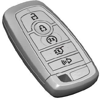
Passive Key

The passive key operates the power locks and the remote start system. The passive key must be in your vehicle to use the push button start.
Note: You may not be able to shift out of park (P) unless the passive key is inside your vehicle.
