Lincoln Aviator: Starting a Gasoline Engine / Stopping the Engine When Your Vehicle is Stationary

  1. Shift into park (P).
  2. Press the push button ignition switch.
  3. Apply the parking brake.

Note: The ignition, all electrical circuits and all warning lamps and indicators will be turned off.

Note: If the engine is idling for 30 minutes, the ignition and engine shut down.

Vehicles using Phone as a Key

  1. Shift into park (P).
  2. Press the push button ignition switch.
  3. Apply the parking brake.

Note: The ignition, all electrical circuits and all warning lamps and indicators will be turned off.

Note: If the engine is idling for 30 minutes, the ignition and engine shut down.

    Automatic Engine Shutdown

    This feature shuts down the engine if it has been idling for an extended period. The ignition also turns off in order to save battery power. Before your vehicle shuts down, a message appears in the information display showing a timer counting down from 30 seconds...

    Stopping the Engine When Your Vehicle is Moving

    WARNING: Switching off the engine when your vehicle is still moving results in a significant decrease in braking assistance. Higher effort is required to apply the brakes and to stop your vehicle...

    Other information:

    Lincoln Aviator 2020-2025 Owners Manual: Child Restraint and Seatbelt Maintenance


    Inspect the vehicle seatbelts and child safety seat systems periodically to make sure they work properly and are not damaged. Inspect the vehicle and child restraint seatbelts to make sure there are no nicks, tears or cuts. Replace if necessary. All vehicle seatbelt assemblies, including retractors, buckles, front seatbelt buckle assemblies, buckle support assemblies (slide bar-if equipped), shoulder belt height adjusters (if equipped), shoulder belt guide on seat backrest (if equipped), child safety seat LATCH and tether anchors, and attaching hardware, should be inspected after a crash...

    Lincoln Aviator 2020-2025 Service Manual: Diagnosis and Testing - Vehicle Dynamic Suspension


    Diagnostic Trouble Code (DTC) Chart Diagnostics in this manual assume a certain skill level and knowledge of Ford-specific diagnostic practices. REFER to: Diagnostic Methods (100-00 General Information, Description and Operation).   Diagnostic Trouble Code Chart Module   DTC Description Action   VDM C110C:11 Left Front Damper Solenoid: Circuit Short to Ground   GO to Pinpoint Test D   VDM C110C:12 Left Front Damper Solenoid: Circuit Short to Battery   GO to Pinpoint Test D   VDM C110C:13 Left Front Damper Solenoid: Circuit Open   GO to Pinpoint Test D   VDM C110C:64 Left Front Damper Solenoid:Signal Plausibility Failure   GO to Pinpoint Test D   VDM C110D:11 Right Front Damper Solenoid: Circuit Short to Ground   GO to Pinpoint Test E   VDM C110D:12 Right Front Damper Solenoid: Circuit Short to Battery   GO to Pinpoint Test E   VDM C110D:13 Right Front Damper Solenoid: Circuit Open   GO to Pinpoint Test E   VDM C110D:64 Right Front Damper Solenoid:Signal Plausibility Failure   GO to Pinpoint Test E   VDM C110E:11 Left Rear Damper Solenoid: Circuit Short to Ground   GO to Pinpoint Test F   VDM C110E:12 Left Rear Damper Solenoid: Circuit Short to Battery   GO to Pinpoint Test F   VDM C110E:13 Left Rear Damper Solenoid: Circuit Open   GO to Pinpoint Test F   VDM C110E:64 Left Rear Damper Solenoid:Signal Plausibility Failure   GO to Pinpoint Test F   VDM C110F:11 Right Rear Damper Solenoid: Circuit Short to Ground   GO to Pinpoint Test G   VDM C110F:12 Right Rear Damper Solenoid: Circuit Short to Battery   GO to Pinpoint Test G   VDM C110F:13 Right Rear Damper Solenoid: Circuit Open   GO to Pinpoint Test G   VDM C110F:64 Right Rear Damper Solenoid:Signal Plausibility Failure   GO to Pinpoint Test G   VDM C1124:55 Height Sensor(s):Not Configured   GO to Pinpoint Test U   VDM C1124:56 Height Sensor(s):Invalid/Incompatible Configuration   GO to Pinpoint Test U   VDM C1A03:11 Left Front Height Sensor: Circuit Short to Ground   GO to Pinpoint Test H   VDM C1A03:12 Left Front Height Sensor: Circuit Short to Battery   GO to Pinpoint Test H   VDM C1A03:29 Left Front Height Sensor:Signal Invalid   GO to Pinpoint Test H   VDM C1A03:64 Left Front Height Sensor:Signal Plausibility Failure   GO to Pinpoint Test T   VDM C1A04:11 Right Front Height Sensor: Circuit Short to Ground   GO to Pinpoint Test I   VDM C1A04:12 Right Front Height Sensor: Circuit Short to Battery   GO to Pinpoint Test I   VDM C1A04:29 Right Front Height Sensor:Signal Invalid   GO to Pinpoint Test I   VDM C1A04:64 Right Front Height Sensor:Signal Plausibility Failure   GO to Pinpoint Test T   VDM C1A05:11 Left Rear Height Sensor: Circuit Short to Ground   GO to Pinpoint Test J   VDM C1A05:12 Left Rear Height Sensor: Circuit Short to Battery   GO to Pinpoint Test J   VDM C1A05:29 Left Rear Height Sensor:Signal Invalid   GO to Pinpoint Test J   VDM C1A05:64 Left Rear Height Sensor:Signal Plausibility Failure   GO to Pinpoint Test T   VDM C1A06:11 Right Rear Height Sensor: Circuit Short to Ground   GO to Pinpoint Test K   VDM C1A06:12 Right Rear Height Sensor: Circuit Short to Battery   GO to Pinpoint Test K   VDM C1A06:29 Right Rear Height Sensor:Signal Invalid   GO to Pinpoint Test K   VDM C1A06:64 Right Rear Height Sensor:Signal Plausibility Failure   GO to Pinpoint Test T   VDM P1758:19 Pressure Solenoid Control System Incorrect Current: Circuit Current Above Threshold   GO to Pinpoint Test C   VDM U0100:87 Lost Communication With ECM / PCM: Missing Message   GO to Pinpoint Test M   VDM U0121:87 Lost Communication With Anti-Lock Brake System (ABS) Control Module: Missing Message   GO to Pinpoint Test N   VDM U0131:87 Lost Communication With EPAS module: Missing Message   GO to Pinpoint Test O   VDM U0140:87 Lost Communication With Body Control Module: Missing Message   GO to Pinpoint Test P   VDM U0151:87 Lost Communication With Restraints Control Module: Missing Message   GO to Pinpoint Test Q   VDM U0164:87 Lost Communication With HVAC Control Module:Missing Message   GO to Pinpoint Test R   VDM U023A:87 Lost Communication With Image Processing Module A:Missing Message   GO to Pinpoint Test S   VDM U0401:00 Invalid Data Received from ECM/PCM A:No Sub Type Information   GO to Pinpoint Test W   VDM U0415:00 Invalid Data Received from Anti-Lock Brake System (ABS) Control Module "A":No Sub Type Information   GO to Pinpoint Test X   VDM U0420:00 Invalid Data Received from Power Steering Control Module "A":No Sub Type Information   GO to Pinpoint Test Y   VDM U0422:00 Invalid Data Received From Body Control Module:No Sub Type Information   GO to Pinpoint Test Z   VDM U0424:00 Invalid Data Received From HVAC Control Module:No Sub Type Information   GO to Pinpoint Test AA   VDM U0452:00 Invalid Data Received From Restraints Control Module:No Sub Type Information   GO to Pinpoint Test AB   VDM U053B:00 Invalid Data Received From Image Processing Module A:No Sub Type Information   GO to Pinpoint Test AC   VDM U1000:00 Solid State Driver Protection Active -Driver Disabled:No Sub Type Information   GO to Pinpoint Test V   VDM U200D:11 Control Module Output Power A: Circuit Short to Ground   GO to Pinpoint Test L   VDM U200D:12 Control Module Output Power A: Circuit Short to Battery   GO to Pinpoint Test L   VDM U200E:11 Control Module Output Power B: Circuit Short to Ground   GO to Pinpoint Test L   VDM U200E:12 Control Module Output Power B: Circuit Short to Battery   GO to Pinpoint Test L   VDM U200F:11 Control Module Output Power C:Circuit Short To Ground   GO to Pinpoint Test J   VDM U200F:12 Control Module Output Power C:Circuit Short To Battery   GO to Pinpoint Test J   VDM U201E:11 Control Module Output Power D:Circuit Short To Ground   GO to Pinpoint Test K   VDM U201E:12 Control Module Output Power D:Circuit Short To Battery   GO to Pinpoint Test K   VDM U2024:51 Control Module Cal-Config Data:Not Programmed   GO to Pinpoint Test V   VDM U2100:00 Initial Configuration Not Complete:No Sub Type Information   GO to Pinpoint Test V   VDM U2200:00 Control Module Configuration Memory Corrupt:No Sub Type Information   GO to Pinpoint Test V   VDM U3000:04 Control Module:System Internal Failures   GO to Pinpoint Test V   VDM U3000:49 Control Module:Internal Electronic Failure   GO to Pinpoint Test V   VDM U3003:16 Battery Voltage: Circuit Voltage Below Threshold   GO to Pinpoint Test A   VDM U3003:17 Battery Voltage: Circuit Voltage Above Threshold   GO to Pinpoint Test B Symptom Chart Symptom Chart: Vehicle Dynamic Suspension Diagnostics in this manual assume a certain skill level and knowledge of Ford-specific diagnostic practices...

    Categories

    Adjusting the Steering Wheel - Vehicles With: Manual Adjustable Steering Column

    WARNING: Do not adjust the steering wheel when your vehicle is moving.

    Note: Make sure that you are sitting in the correct position.

    Unlock the steering column. Adjust the steering wheel to the desired position.
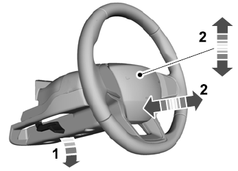
    Lincoln Aviator. Column

    Lock the steering column.

    read more

     
    Copyright © 2025 www.liaviator2.com