Lincoln Aviator: Introduction / Symbols Glossary
These are some of the symbols you may see on your vehicle.
 Air conditioning system
 Air conditioning system lubricant
type
Air conditioning system lubricant
type
 Anti-lock braking system
 Avoid smoking, flames or sparks
 Battery
 Battery acid
 Brake fluid - non petroleum based
 Brake system
 Brake system
 Cabin air filter
 Check fuel cap
 Child safety door lock or unlock
 Child seat lower anchor
 Child seat tether anchor
 Cruise control
 Do not open when hot
 Engine air filter
 Engine coolant
 Engine coolant temperature
 Engine oil
 Explosive gas
 Fan warning
 Fasten seatbelt
 Flammable
 Front airbag
 Front fog lamps
 Fuel pump reset
 Fuse compartment
 Hazard flashers
 Heated rear window
 Windshield defrosting system
 Interior luggage compartment
release
Interior luggage compartment
release
 Jack
Jack
 Keep out of reach of children
 Lighting control
 Low tire pressure warning
 Maintain correct fluid level
 Note operating instructions
 Horn control
 Panic alarm
 Parking aid
 Parking brake
 Power steering fluid
 Power windows front/rear
 Power window lockout
 Requires registered technician
 Safety alert
 See Owner's Manual
 See Service Manual
 Service engine soon
 Passenger airbag activated
 Passenger airbag deactivated
 Side airbag
 Shield the eyes
 Stability control
 Hill descent control
 Trail control
 Windshield wiping system
 Windshield wash and wipe
 About This Manual
Thank you for choosing Lincoln. We
recommend that you take some time to get
to know your vehicle by reading this manual.
The more that you know about it, the greater
the safety and pleasure you will get from
driving it...
 Perchlorate
Certain components in your vehicle such as
airbag modules, seatbelt pretensioners and
remote control batteries may contain
perchlorate material. Special handling may
apply for service or vehicle end of life
disposal...
Other information:
Lincoln Aviator 2020-2026 Service Manual: Removal and Installation - Drive Pinion Seal
Special Tool(s) / General Equipment 205-1065Installer, Pinion Seal 205-199 (T83T-3132-A1) Installer, Spindle/Axle ShaftT83-4000-ATKIT-1983-FTKIT-1983-FLMTKIT-1983-FX Flat Headed Screw Driver Materials Name Specification Motorcraft® High Temperature 4x4 Front Axle and Wheel Bearing GreaseXG-11 WSS-M1C267-A1 Removal Remove the front driveshaft...
Lincoln Aviator 2020-2026 Service Manual: General Procedures - Brake Service Mode Activation and Deactivation
Activation WARNING: Service actions on vehicles equipped with electronic parking brakes may cause unexpected parking brake application, which could result in injury to hands or fingers. Put the electronic parking brake system into service mode prior to servicing or removing rear brake components...
Categories
- Manuals Home
- Lincoln Aviator Owners Manual
- Lincoln Aviator Service Manual
- Changing the Front Wiper Blades - Vehicles With: Heated Wiper Blades
- Drive Modes
- Locking and Unlocking
- New on site
- Most important about car
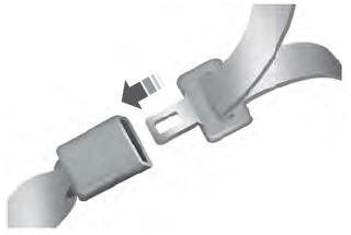
Fastening the Seatbelts
The front outboard and rear safety restraints in the vehicle are combination lap and shoulder belts.
Insert the belt tongue into the proper buckle (the buckle closest to the direction the tongue is coming from) until you hear a snap and feel it latch. Make sure that you securely fasten the tongue in the buckle.