
Lincoln Aviator: Hill Descent Control / What Is Hill Descent Control
WARNING: Hill descent control cannot control descent in all surface conditions and circumstances, such as ice or extremely steep grades. Hill descent control is a driver assist system and cannot substitute for good judgment by the driver. Failure to do so may result in loss of vehicle control, crash or serious injury.
WARNING: The system does not replace the parking brake. When you leave your vehicle, always apply the parking brake and shift the transmission into park (P) for automatic transmission or first gear for manual transmission.
Note: The system does not function below 3 mph (5 km/h).
Hill descent control allows the driver to set and maintain vehicle speed while descending steep slopes in various surface conditions.
The system can maintain vehicle speeds on downhill slopes between 3–20 mph (5–32 km/h). Above 20 mph (32 km/h), the system remains on but the descent speed cannot be set or maintained.
The system requires a cool down interval after a period of sustained use. The amount of time that the system can remain active before cooling varies with conditions. The system provides a warning in the message center and a tone sounds when the system is about to disengage for cooling. At this time, manually apply the brakes as needed to maintain descent speed.

 Switching Hill Descent Control On and Off. Setting the Hill Descent Speed
Switching Hill Descent Control On and Off
You can switch the hill descent control on
and off through the touchscreen.
Setting the Hill Descent Speed
WARNING: The system does not
replace the parking brake...
Other information:
Lincoln Aviator 2020-2026 Service Manual: Description and Operation - Climate Control System - Overview
Vehicles with: Dual Automatic Temperature Control (DATC) Overview The DATC system maintains the selected vehicle interior temperature by heating and/or cooling the air depending on the HVAC control panel selection. The driver may override the automatic mode of operation...
Lincoln Aviator 2020-2026 Owners Manual: Settings Data
Your vehicle has electronic control units that have the ability to store data based on your personalized settings. The data is stored locally in the vehicle or on devices that you connect to it, for example, a USB drive or digital music player. You can delete some of this data and also choose whether to share it through the services to which you subscribe...
Categories
- Manuals Home
- Lincoln Aviator Owners Manual
- Lincoln Aviator Service Manual
- Body and Paint
- Description and Operation - Jacking and Lifting
- Changing the Front Wiper Blades - Vehicles With: Heated Wiper Blades
- New on site
- Most important about car
Locking and Unlocking the Doors from Inside
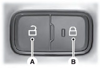
Locking the Doors
Press the lock switch on the door interior trim panel. The doors can no longer be released using the exterior door handle switches and the luggage compartment locks.
