Lincoln Aviator: Pre-Collision Assist / Blocked Sensors
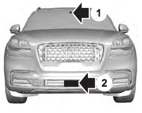
- Camera.
- Radar sensor (if equipped).
If a message regarding a blocked sensor or camera appears in the information display, the radar signals or camera images are obstructed. If your vehicle has a radar sensor, it is behind the fascia cover in the center of the lower grille. With a blocked sensor or camera, the Pre-Collision Assist system may not function, or performance may reduce. The following table lists possible causes and actions for when this message displays.
Camera Troubleshooting
Radar Troubleshooting (If Equipped)
Note: Proper system operation requires a clear view of the road by the camera. Have any windshield damage in the area of the camera's field of view repaired.
Note: If something hits the front end of your vehicle or damage occurs and your vehicle has a radar sensor, the radar sensing zone may change. This could cause missed or false detections. Contact an authorized dealer to have the radar checked for proper coverage and operation.
 Adjusting the Pre-Collision Assist Settings
You can adjust the following settings by
using the information display controls.
You can change Alert and Distance Alert
sensitivity to one of three possible
settings...

Other information:
Lincoln Aviator 2020-2026 Service Manual: Removal and Installation - Crankshaft Front Seal
Special Tool(s) / General Equipment 303-1531Installer, Front Crank Seal and Damper 303-335 (T88T-6701-A) Installer, Front Cover Oil SealTKIT-1988-FLMTKIT-1988-F 303-409 (T92C-6700-CH) Remover, Crankshaft SealTKIT-1992-FH/FMH/FLMHTKIT-1993-LMH/MH Removal Remove the crankshaft pulley...
Lincoln Aviator 2020-2026 Service Manual: Description and Operation - Fuel Charging and Controls - System Operation and Component Description
System Operation Air Fuel Ratio Imbalance Monitor The air fuel ratio imbalance monitor is an on board diagnostic strategy designed to monitor the air fuel ratio. Air Fuel Ratio Imbalance Monitor — Heated Oxygen Sensor (HO2S) Monitor The air fuel ratio imbalance monitor estimates the cylinder to cylinder air fuel ratio difference using the universal HO2S high frequency signal...
Categories
- Manuals Home
- Lincoln Aviator Owners Manual
- Lincoln Aviator Service Manual
- Wireless Accessory Charger (If Equipped)
- Remove and Reinstall the Battery
- Description and Operation - Body and Frame
- New on site
- Most important about car
Emergency Locking
Each door has a backup power system which allows the door to function if your vehicle has no power. The system has a limited number of operations before the power is depleted and turns off. When the system turns off, the door remains open and unlatched and does not close.
If your vehicle has no power and the backup power system is turned off, you can close and secure your vehicle by manually resetting each door latch using a key in the position shown.