Lincoln Aviator 2020-2025 Service Manual / Powertrain / Engine / Engine Cooling - 3.0L EcoBoost / Description and Operation - Engine Cooling - Component Location

Lincoln Aviator: Engine Cooling - 3.0L EcoBoost / Description and Operation - Engine Cooling - Component Location

NOTE: Coolant temperature will vary with ambient temperature and load. Temperatures shown are for ambient temperature of 38° C (100° F). Red arrows indicate a temperature over 90° C (194° F), Orange arrows indicate a temperature of approximately 90° C (194° F), Blue arrows indicate a temperature below 90° C (194° F).

Base models


Item Description
1 Radiator
2 Degas bottle
3 Engine-to-degas bottle hose
4 Radiator-to-degas bottle hose
5 Heater hose assembly
6 A/C assembly
7 Cylinder head to coolant outlet connector hose RH
8 Coolant outlet connector hose
9 Coolant outlet connector
10 Turbocharger inlet tube LH
11 Turbocharger LH
12 Turbocharger outlet tube LH
13 Engine oil cooler outlet hose
14 Upper radiator hose
15 Engine oil cooler
16 Coolant pump
17 Lower radiator hose
18 Degas bottle hose
19 Engine oil cooler
20 Transmission oil cooler
21 Engine front cover
22 Cylinder block
23 Cylinder head gasket
24 Cylinder head LH
25 Cylinder head to coolant outlet connector hose LH
26 Cabin heater coolant pump outlet hose
27 Cabin heater coolant pump inlet hose
28 Cabin heater coolant pump
29 Turbocharger outlet tube RH
30 Turbocharger inlet tube RH
31 Turbocharger RH
32 Evaporator
33 Heater hose assembly
34 Transmission oil cooler inlet hose
35 Transmission coolant control valve
36 Coolant pump outlet hose
37 Engine oil cooler inlet hose

Police models


Item Description
1 Radiator
2 Degas bottle
3 Radiator-to-degas bottle hose
4 Engine-to-degas bottle hose
5 Coolant outlet connector hose
6 Cylinder head to coolant outlet connector hose RH
7 Coolant outlet connector
8 Turbocharger inlet tube LH
9 Turbocharger LH
10 Turbocharger outlet tube LH
11 Engine oil cooler outlet hose
12 Upper radiator hose
13 Lower radiator hose
14 Degas bottle hose
15 Engine front cover
16 Coolant pump
17 Engine oil cooler
18 Cylinder head LH
19 Cylinder head gasket
20 Cylinder head to coolant outlet connector hose LH
21 Turbocharger outlet tube RH
22 Turbocharger RH
23 Turbocharger inlet tube RH
24 Cylinder block
25 Heater hose assembly
26 Coolant reservoir bracket
27 Evaporator
28 Transmission oil cooler
29 Transmission oil cooler inlet hose
30 Transmission oil cooler outlet hose
31 Transmission coolant control valve
32 Coolant pump outlet hose
33 Engine oil cooler inlet hose

    Specifications

    Lubricants, Fluids, Sealants and Adhesives Name Specification Fill Capacity Motorcraft® Yellow Concentrated Antifreeze/CoolantVC-13-G WSS-M97B57-A1  16...

    Description and Operation - Engine Cooling - System Operation and Component Description

    System Operation Engine coolant flows primarily from the engine to the radiator circuit and back to the coolant pump. Coolant is sent from the coolant pump through the engine block and cylinder heads...

    Other information:

    Lincoln Aviator 2020-2025 Service Manual: Removal and Installation - Rear Evaporator


    Removal NOTE: Removal steps in this procedure may contain installation details. Remove the rear climate control housing. Refer to: Rear Climate Control Housing (412-02A Rear Climate Control, Removal and Installation). NOTE: Replace the pass-through floor seal with new if seal is removed or damaged...

    Lincoln Aviator 2020-2025 Service Manual: Diagnosis and Testing - Vehicle Dynamic Suspension - Vehicles With: Air Suspension


    Diagnostic Trouble Code (DTC) Chart Diagnostics in this manual assume a certain skill level and knowledge of Ford-specific diagnostic practices. REFER to: Diagnostic Methods (100-00 General Information, Description and Operation).   Diagnostic Trouble Code Chart Module   DTC Description Action   SUMA B1041:52 Levelling Control: Not Activated   GO to Pinpoint Test W   SUMA C1043:00 Pressure Decrease Too Slow From Reservoir: No Sub Type Information   GO to Pinpoint Test M   SUMA C104C:11 Left Rear Spring Rate Valve: Circuit Short To Ground   GO to Pinpoint Test E   SUMA C104C:12 Left Rear Spring Rate Valve: Circuit Short To Battery   GO to Pinpoint Test E   SUMA C104C:13 Left Rear Spring Rate Valve: Circuit Open   GO to Pinpoint Test E   SUMA C104C:1A Left Rear Spring Rate Valve: Circuit Resistance Below Threshold   GO to Pinpoint Test E   SUMA C104C:1F Left Rear Spring Rate Valve: Circuit Intermittent   GO to Pinpoint Test E   SUMA C104D:11 Right Front Spring Rate Valve: Circuit Short To Ground   GO to Pinpoint Test D   SUMA C104D:12 Right Front Spring Rate Valve: Circuit Short To Battery   GO to Pinpoint Test D   SUMA C104D:13 Right Front Spring Rate Valve: Circuit Open   GO to Pinpoint Test D   SUMA C104D:1A Right Front Spring Rate Valve: Circuit Resistance Below Threshold   GO to Pinpoint Test D   SUMA C104D:1F Right Front Spring Rate Valve: Circuit Intermittent   GO to Pinpoint Test D   SUMA C104E:11 Right Rear Spring Rate Valve: Circuit Short To Ground   GO to Pinpoint Test F   SUMA C104E:12 Right Rear Spring Rate Valve: Circuit Short To Battery   GO to Pinpoint Test F   SUMA C104E:13 Right Rear Spring Rate Valve: Circuit Open   GO to Pinpoint Test F   SUMA C104E:1A Right Rear Spring Rate Valve: Circuit Resistance Below Threshold   GO to Pinpoint Test F   SUMA C104E:1F Right Rear Spring Rate Valve: Circuit Intermittent   GO to Pinpoint Test F   SUMA C104F:11 Left Front Spring Rate Valve: Circuit Short To Ground   GO to Pinpoint Test C   SUMA C104F:12 Left Front Spring Rate Valve: Circuit Short To Battery   GO to Pinpoint Test C   SUMA C104F:13 Left Front Spring Rate Valve: Circuit Open   GO to Pinpoint Test C   SUMA C104F:1A Left Front Spring Rate Valve: Circuit Resistance Below Threshold   GO to Pinpoint Test C   SUMA C104F:1F Left Front Spring Rate Valve: Circuit Intermittent   GO to Pinpoint Test C   SUMA C1124:07 Height Sensor(s): Mechanical Failures   GO to Pinpoint Test G   SUMA C1124:11 Height Sensor(s): Circuit Short To Ground   GO to Pinpoint Test H   SUMA C1124:12 Height Sensor(s): Circuit Short To Battery   GO to Pinpoint Test H   SUMA C1124:54 Height Sensor(s): Missing Calibration   GO to Pinpoint Test U   SUMA C1A03:2A Left Front Height Sensor: Stuck in Range   GO to Pinpoint Test I   SUMA C1A03:34 Left Front Height Sensor: Signal High Time Less Than Minimum   GO to Pinpoint Test I   SUMA C1A03:35 Left Front Height Sensor: Signal High Time Greater Than Maximum   GO to Pinpoint Test I   SUMA C1A03:36 Left Front Height Sensor: Signal Frequency Too Low   GO to Pinpoint Test I   SUMA C1A03:37 Left Front Height Sensor: Signal Frequency Too High   GO to Pinpoint Test I   SUMA C1A03:84 Left Front Height Sensor: Signal Below Allowable Range   GO to Pinpoint Test I   SUMA C1A03:85 Left Front Height Sensor: Signal Above Allowable Range   GO to Pinpoint Test I   SUMA C1A04:2A Right Front Height Sensor: Stuck in Range   GO to Pinpoint Test J   SUMA C1A04:34 Right Front Height Sensor: Signal High Time Less Than Minimum   GO to Pinpoint Test J   SUMA C1A04:35 Right Front Height Sensor: Signal High Time Greater Than Maximum   GO to Pinpoint Test J   SUMA C1A04:36 Right Front Height Sensor: Signal Frequency Too Low   GO to Pinpoint Test J   SUMA C1A04:37 Right Front Height Sensor: Signal Frequency Too High   GO to Pinpoint Test J   SUMA C1A04:84 Right Front Height Sensor: Signal Below Allowable Range   GO to Pinpoint Test J   SUMA C1A04:85 Right Front Height Sensor: Signal Above Allowable Range   GO to Pinpoint Test J   SUMA C1A05:2A Left Rear Height Sensor: Stuck in Range   GO to Pinpoint Test K   SUMA C1A05:34 Left Rear Height Sensor: Signal High Time Less Than Minimum   GO to Pinpoint Test K   SUMA C1A05:35 Left Rear Height Sensor: Signal High Time Greater Than Maximum   GO to Pinpoint Test K   SUMA C1A05:36 Left Rear Height Sensor: Signal Frequency Too Low   GO to Pinpoint Test K   SUMA C1A05:37 Left Rear Height Sensor: Signal Frequency Too High   GO to Pinpoint Test K   SUMA C1A05:84 Left Rear Height Sensor: Signal Below Allowable Range   GO to Pinpoint Test K   SUMA C1A05:85 Left Rear Height Sensor: Signal Above Allowable Range   GO to Pinpoint Test K   SUMA C1A06:2A Right Rear Height Sensor: Stuck in Range   GO to Pinpoint Test L   SUMA C1A06:34 Right Rear Height Sensor: Signal High Time Less Than Minimum   GO to Pinpoint Test L   SUMA C1A06:35 Right Rear Height Sensor: Signal High Time Greater Than Maximum   GO to Pinpoint Test L   SUMA C1A06:36 Right Rear Height Sensor: Signal Frequency Too Low   GO to Pinpoint Test L   SUMA C1A06:37 Right Rear Height Sensor: Signal Frequency Too High   GO to Pinpoint Test L   SUMA C1A06:84 Right Rear Height Sensor: Signal Below Allowable Range   GO to Pinpoint Test L   SUMA C1A06:85 Right Rear Height Sensor: Signal Above Allowable Range   GO to Pinpoint Test L   SUMA C1A20:00 Pressure Increase Too Slow When Filling Reservoir: No Sub Type Information   GO to Pinpoint Test M   SUMA C1A27:09 Compressor: Component Failures   GO to Pinpoint Test N   SUMA C1A27:63 Compressor: Circuit/Component Protection Time-Out   GO to Pinpoint Test N   SUMA C1A27:98 Compressor: Component Or System Over Temperature   GO to Pinpoint Test N   SUMA C1A27:99 Compressor: Exceeded Learning Limit   GO to Pinpoint Test N   SUMA C1A31:63 Left Front Corner Valve: Circuit/Component Protection Time-Out   GO to Pinpoint Test AD   SUMA C1A32:63 Right Front Corner Valve: Circuit/Component Protection Time-Out   GO to Pinpoint Test AD   SUMA C1A33:63 Left Rear Corner Valve: Circuit/Component Protection Time-Out   GO to Pinpoint Test AD   SUMA C1A34:63 Right Rear Corner Valve: Circuit/Component Protection Time-Out   GO to Pinpoint Test AD   SUMA C1A36:63 Exhaust Valve: Circuit/Component Protection Time-Out   GO to Pinpoint Test AD   SUMA U0100:87 Lost Communication With ECM / PCM: Missing Message   GO to Pinpoint Test O   SUMA U0121:87 Lost Communication With Anti-Lock Brake System (ABS) Control Module: Missing Message   GO to Pinpoint Test P   SUMA U0122:87 Lost Communication With Vehicle Dynamics Control Module: Missing Message   GO to Pinpoint Test Q   SUMA U0131:87 Lost Communication With Power Steering Control Module "A": Missing Message   GO to Pinpoint Test R   SUMA U0140:87 Lost Communication With Body Control Module: Missing Message   GO to Pinpoint Test S   SUMA U0146:87 Lost Communication With Serial Data Gateway "A": Missing Message   GO to Pinpoint Test T   SUMA U0401:00 Invalid Data Received from ECM/PCM A: No Sub Type Information   GO to Pinpoint Test X   SUMA U0415:00 Invalid Data Received from Anti-Lock Brake System (ABS) Control Module "A": No Sub Type Information   GO to Pinpoint Test Y   SUMA U0416:00 Invalid Data Received From Vehicle Dynamics Control Module: No Sub Type Information   GO to Pinpoint Test Z   SUMA U0420:00 Invalid Data Received from Power Steering Control Module "A": No Sub Type Information   GO to Pinpoint Test AA   SUMA U0422:00 Invalid Data Received From Body Control Module: No Sub Type Information   GO to Pinpoint Test AB   SUMA U0447:00 Invalid Data Received From Serial Data Gateway "A": No Sub Type Information   GO to Pinpoint Test AC   SUMA U2100:00 Initial Configuration Not Complete: No Sub Type Information   GO to Pinpoint Test V   SUMA U2100:56 Initial Configuration Not Complete: Invalid/Incompatible Configuration   GO to Pinpoint Test V   SUMA U3000:04 Control Module: System Internal Failures   GO to Pinpoint Test V   SUMA U3000:45 Control Module: Program Memory Failure   GO to Pinpoint Test V   SUMA U3000:46 Control Module: Calibration/Parameter Memory Failure   GO to Pinpoint Test V   SUMA U3000:47 Control Module: Watchdog/Safety µC Failure   GO to Pinpoint Test V   SUMA U3000:48 Control Module: Supervision Software Failure   GO to Pinpoint Test V   SUMA U3003:16 Battery Voltage: Circuit Voltage Below Threshold   GO to Pinpoint Test A   SUMA U3003:17 Battery Voltage: Circuit Voltage Above Threshold   GO to Pinpoint Test B Symptom Chart Symptom Chart: Vehicle Dynamic Suspension Diagnostics in this manual assume a certain skill level and knowledge of Ford-specific diagnostic practices...

    Categories

    Adjusting the Steering Wheel - Vehicles With: Manual Adjustable Steering Column

    WARNING: Do not adjust the steering wheel when your vehicle is moving.

    Note: Make sure that you are sitting in the correct position.

    Unlock the steering column. Adjust the steering wheel to the desired position.
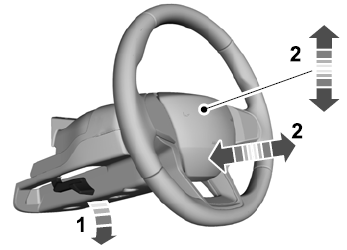
    Lincoln Aviator. Column

    Lock the steering column.

    read more

     
    Copyright © 2025 www.liaviator2.com