Lincoln Aviator: Glass, Frames and Mechanisms / Description and Operation - Glass, Frames and Mechanisms - Overview
Overview
Power Windows
The power windows operate only when the accessory delay relay is active. The accessory delay relay is active whenever the ignition is on, or up to 10 minutes after the ignition is changed from on to off while the front driver and passenger doors remain closed.
Power Window Operation
Standard power window features include one-touch up and one-touch down operation on all 4 doors. The window control switch:
- can manually or automatically raise/lower all windows from the driver window control switch or the individual passenger window from the corresponding door switch.
- has a rear passenger window lock-out feature (located on the driver window control switch).
Global Open/Close
The RKE can be used to operate the windows when the ignition is off and the accessory delay feature is not active. Within a short time after unlocking the vehicle doors with the RKE transmitter, press and hold the unlock button on the RKE transmitter until the windows begin moving. The windows automatically open. To close the windows, press and hold the lock button on the RKE transmitter until the windows begin moving. The windows automatically close. Pressing the lock or unlock button while the windows are moving (in either direction) stops window movement.
Rear Window Defrost
Press the rear window defrost switch (integral to the FCIMB) to activate the rear window defrost. The rear window defrost automatically turns off after a short period of time.
 Description and Operation - Glass, Frames and Mechanisms - System Operation and Component Description
System Operation
System Diagram - Power Windows
Driver Side Power Windows
Item
Description
1
LIN
2
Driver Side Front Window Motor
3
Driver Side Rear Window Control Switch
4
Driver Window Control Switch
5
DDM
6
Driver Side Rear Window Motor
Passenger Side Power Windows
Item
Description
1
Passenger Front Window Motor
2
Passenger Rear Window Motor
3
Passenger Side Rear Window Control Switch
4
Passenger Side Front Window Control Switch
5
PDM
6
DDM
7
MS-CAN
Network Message Chart - Power Windows
Passenger Door Module (PDM) Network Input Messages
Broadcast Message
Originating Module
Message Purpose
Passenger window command
DDM
When activating the passenger front or
rear windows from the driver window control switch, the passenger window
command is sent from the DDM to the PDM...
Other information:
Lincoln Aviator 2020-2026 Owners Manual: Child Safety Locks
When the child safety locks are set, you cannot open the rear doors from the inside. The child safety lock control is on the driver door. Press the control to switch the child safety locks on. Press the control again to switch them off. A light on the child safety control illuminates when you switch them on...
Lincoln Aviator 2020-2026 Service Manual: Removal and Installation - Intermediate Speed Sensor A (ISSA)
Removal Remove the main control valve body. Refer to: Main Control Valve Body (307-01A Automatic Transmission - 10-Speed Automatic Transmission – 10R60, Removal and Installation). Remove the intermediate speed sensor A. Slide the plastic lock to the unlocked position...
Categories
- Manuals Home
- Lincoln Aviator Owners Manual
- Lincoln Aviator Service Manual
- Child Safety Locks
- Locking and Unlocking
- USB Port and Power Point Locations
- New on site
- Most important about car
Fastening the Seatbelts
The front outboard and rear safety restraints in the vehicle are combination lap and shoulder belts.
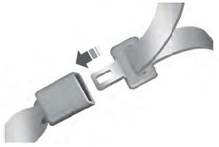
Insert the belt tongue into the proper buckle (the buckle closest to the direction the tongue is coming from) until you hear a snap and feel it latch. Make sure that you securely fasten the tongue in the buckle.

